DCR-SR58E/SR68/SR68E/SR78E/SR88/SR88E_L2
2-6
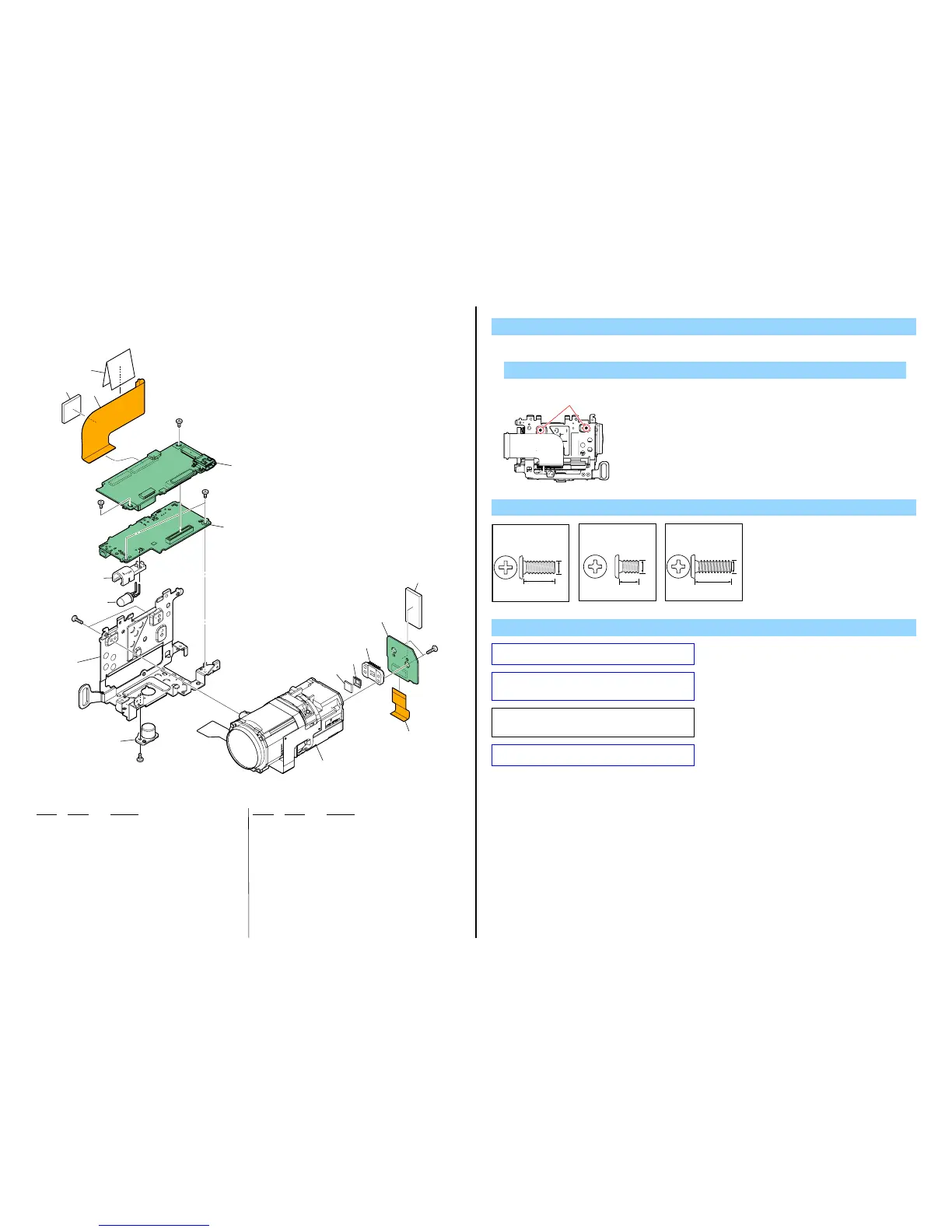
2-1-4. LENS/CHASSIS SECTION
Ref. No. Part No. Description Ref. No. Part No. Description
151 4-173-811-01 SHEET (327), (HDD)
152 1-880-504-11 FP-1217 FLEXIBLE BOARD
153 3-288-685-01 CUSHION, HDD
154 A-1759-340-A VC-587 BOARD, COMPLETE (SERVICE) (Note 3)
155 A-1759-223-A DA-049 BOARD, COMPLETE (SERVICE)
(SR68/SR68E/SR88/SR88E)
155 A-1759-254-A DA-049 BOARD, COMPLETE (SERVICE)
(SR58E/SR78E)
156 4-155-770-01 HOLDER (327), LED
157 X-2514-622-1 FRAME ASSY (327), MAIN
158 3-283-643-01 SCREW, TRIPOD
159 1-788-861-11 OPTICAL UNIT (CK001)
160 1-788-870-11 OPTICAL FILTER BLOCK (Note 2)
161 3-878-748-01 RUBBER (1340), SEAL
162 1-880-150-11 FP-1168 FLEXIBLE BOARD
163 A-1750-996-A CD-786 BOARD, COMPLETE
* 164 4-163-472-01 CUSHION (CD (327))
* D901 6-502-954-01 DI NSPL500DS (Note 4)
IC7101 8-753-331-34 ICX690NKF-H (SR68/SR88) (Note 1)
IC7101 8-753-331-35 ICX691NKF-H (SR58E/SR68E/SR78E/SR88E)
(Note 1)
#2 2-635-562-31 SCREW (M1.7)
#3 2-660-401-01 SCREW (M1.7), NEW TRU-STAR, P2
#12 3-080-204-21 SCREW, TAPPING, P2
1. Remove to numerical order (9 to qa) in the left figure.
DISASSEMBLY
9 #12 X 2
Screw
#2: M1.7 X 4.0
(Black)
2-635-562-31
4.0
1.7
#12
Left View
Note
Note 1: Be sure to read “Precautions for Replacement of Imager”
on page 6-1 when changing the imager.
#3: M1.7 X 2.5
(Red)
2-660-401-01
2.5
1.7
#12: M1.7 X 5.0 (Tapping)
(Black)
3-080-204-21
1.7
5.0
VC-587
DA-049
CD-786
(Note 3)
#3
#3
#3
#2
#12
9 159
162
q; 154
151
152
153
qa 155
IC7101
(Note 1)
#1
160
(Note 2)
161
156
157
163
164
D901
(Note 4)
158
Note 2: Be sure to read “Assembly-1: How to Distinguish The
Side of Optical Filter Block Facing to Lens Device” when
changing the optical filter block.
Note 3: When replacing the VC-587 board, start the Adjust
Manual in the Adjust Station and refer to the “INTERNAL
MEMORY ADJUSTMENTS”.
Note 4: Refer to “Assembly-2:Mounting method of D901 (LED
video light)”.