Do you have a question about the Sony DHR-1000 and is the answer not in the manual?
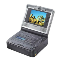
Overview of the DHR-1000's general specifications and features.
Step-by-step procedures for taking the unit apart for servicing.
High-level diagrams illustrating the system's architecture.
Visual documentation of the unit's internal circuitry.
Technical adjustments for the VCR's mechanical components.
Guide to configuring the VCR Plus+ system for initial use.
Instructions on how to record television broadcasts using the VCR.
Explanation of functions and operation of the remote control unit.
How to access and view data recorded on the tape.
Options for choosing audio tracks during playback or recording.
Capturing multi-language or stereo audio content.
Managing scheduled recording timers and settings.
How to fine-tune video display parameters for optimal quality.
Navigating the system menus to modify settings.
Steps to clear data stored in the VCR's cassette memory.
Techniques and procedures for editing recorded video content.
Instructions for duplicating content from one tape to another.
Detailed procedures for calibrating the VCR's mechanical components.
Adjustments for optimizing video signal quality and performance.
Instructions for accessing and utilizing the unit's special service functions.
Information on handling and converting data, including notation formats.
Detailed service mode operations and interpretation of error codes.
Steps to remove the top and side covers for access.
Procedure for detaching the front panel from the unit.
How to properly remove the C door mechanism.
Accessing the TB-28 board for service tasks.
Detaching specific circuit boards (JC-13 and DF-10).
Procedure for safely removing the MD block unit.
Positioning the RP-193 board for recording current checks.
Positioning the CM-49 board for servo and system control adjustments.
Steps to remove the bottom cabinet housing.
Procedure for detaching the tray mechanism assembly.
Steps to remove the T motor assembly.
Procedure for detaching the lower plate of the unit.
Detaching specific board assemblies (VA-93 and YC-144).
Visual diagrams showing the internal layout and components.
Diagram indicating the placement of all circuit boards within the unit.