Do you have a question about the Sony DSR-2000 and is the answer not in the manual?
Optional board for DSR-2000/2000P for i.LINK/DV interface.
Optional remote control panel for DSR-2000/2000P.
Explains the scope and intent of Service Manual Volume 1.
Lists other manuals provided with the DSR-2000/2000P and optional boards.
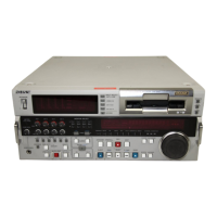
Operating instructions for the DSR-2000 digital videocassette recorder.
Installation instructions for the DSBK-190 i.LINK/DV Input/Output Board.
Installation instructions for the DSBK-200 Remote Control Panel.
Step-by-step guide for installing the DSR-2000/2000P unit.
Specifies suitable operating temperatures, humidity, and locations to avoid.
Details the required power voltage and frequency for operation.
Provides dimensions and clearance requirements for installation.
Lists items included with the unit.
Lists optional accessories available for the unit.
Instructions for mounting the unit in a standard 19-inch rack.
Details the various connectors on the unit.
Covers settings and adjustments required after installation.
Identifies the location of major internal components and boards.
Explains the record proof mechanism for DVCAM cassettes.
Provides instructions for removing and reinstalling the unit's cabinet.
Details the procedure for removing and reinstalling the cassette compartment.
Guides on how to remove and reattach internal circuit boards.
Important considerations when handling repair parts.
Procedure for replacing the internal lithium battery.
Lists necessary fixtures and tools for maintenance.
Guides on updating the unit's system and servo CPU software.
Describes alarms displayed during operation and their countermeasures.
Lists and explains error codes detected by the self-diagnostics function.
Procedures for handling emergency situations.
Overview of the layered maintenance menu structure.
Instructions on navigating and using the maintenance menu.
Details the various items within the maintenance menu.
Lists reference parts and inspection intervals based on hours meter.
Explains how to display and reset accumulated operating hours.
Details maintenance tasks to be performed after repair.
Provides general guidelines and preparation steps for parts replacement.
Step-by-step instructions for replacing the drum assembly.
Procedure for replacing the S/T brake assembly.
Instructions for replacing the brake solenoid.
Steps for replacing the pinch roller assembly.
Procedure for replacing the elevator cam.
Instructions for replacing the pinch solenoid assembly.
Steps for replacing the T-side reel motor assembly.
Procedure for replacing the S-side reel motor assembly.
Instructions for replacing the M stop solenoid assembly.
Steps for replacing the S tension regulator assembly.
Procedure for replacing the T drawer arm assembly.
Instructions for replacing the TG1 arm assembly.
Steps for replacing the TG8 arm assembly.
Procedure for replacing the rail assembly.
Instructions for replacing the capstan motor.
Steps for replacing the loading motor assembly.
Procedure for replacing the reel shift motor assembly.
Instructions for replacing the MIC assembly.
Steps for replacing the MIC holder assembly.
Procedure for replacing the HC roller assembly.
Instructions for replacing the head cleaner solenoid.
Steps for replacing the cassette compartment motor.
Procedure for replacing the switching regulator.
Provides general information and tools needed for tape path adjustment.
Details the procedure for adjusting the tape path.
Describes how to adjust the RF switching position.
Explains how to confirm correct tape path adjustment.
Procedure to check waveform during x5 search forward.
Procedure to check waveform during x5 search reverse.
Checks RF waveform raiseup during mode changes.
How to check tape curl at various tape guides.
Lists adjustments and checks required after replacing specific boards.
Provides an overview of electrical alignment procedures and required equipment.
Covers adjustments for audio output and EE levels.
Detailed procedures for various video signal adjustments.
| Video Format | DVCAM/DV |
|---|---|
| Audio | 16-bit/48 kHz or 12-bit/32 kHz |
| Video Standard | NTSC/PAL |
| Power Requirements | AC 100-240V, 50/60Hz |
| Recording Time | Up to 184 minutes (with DVM-184 tape) |
| Audio Tracks | 4 |
| Input/Output Connectors | Composite, S-Video, XLR, RCA |
| Tape Speed | DVCAM: 28.2 mm/s, DV: 18.8 mm/s |
| Display | Built-in LCD monitor |