1
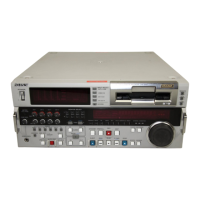
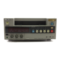
DSR-2000/2000P
Table of Contents
Manual Structure
Purpose of this manual .............................................................................................. 7
Related manuals......................................................................................................... 7
Contents ..................................................................................................................... 8
1. Operating Instructions
1-1. DSR-2000....................................................................................................1-1
1-2. DSBK-190.................................................................................................1-81
1-3. DSBK-200.................................................................................................1-86
2. Installation
2-1. Installation Procedure.................................................................................. 2-1
2-2. Operational Environment ............................................................................2-1
2-3. Operating Voltage .......................................................................................2-1
2-4. Installation Space ........................................................................................2-2
2-5. Supplied Accessories ..................................................................................2-2
2-6. Optional Accessories...................................................................................2-2
2-7. Rack Mounting............................................................................................2-3
2-8. Connectors...................................................................................................2-5
2-8-1. Connectors/Cables......................................................................2-5
2-8-2. Input/Output Signals of the Connectors .....................................2-6
2-9. Installation Setup and Adjustment ............................................................2-10
2-9-1. Switch Settings on the Connector Panel ..................................2-10
2-9-2. Front Panel Setting ...................................................................2-11
2-9-3. On-board Switch Setting ..........................................................2-12
2-9-4. System Adjustment After Installation ......................................2-14
3. Service Overview
3-1. Location of Main Parts................................................................................3-1
3-1-1. Location of Printed Circuit Boards ............................................3-1
3-1-2. Location of Main Mechanical Parts ...........................................3-6
3-1-3. Location of Sensors .................................................................... 3-7
3-2. Functions of Record Proof Hole and Record Proof Plug of Cassette .........3-9
3-3. Removal/Installation of Cabinet ...............................................................3-10
3-4. Removal/Reattachment of the Cassette Compartment..............................3-13