3-15
DSR-2000/2000P
CP-342 board
Screws
BVTP3 x 8
Screw
BVTP3 x 8
Screws
BVTP3 x 8
CN601
CN602
CN603
CN604
CN605
Screws for
connector
CP-341 board
CN608
CN606
CN607
Screws
BVTT3 x 6
Connectors
(MB-859 board)
Connctor panel
Screws
BVTT3 x 6
White
Red
Black
Green
Orange
Yellow
Blue
3-5-3. Removal/Reattachment of the Boards
n
Turn off the power of the unit before removing.
Tools
. Torque screwdriver’s bit (for M3) : J-6325-110-A
. Torque screwdriver (3kg) : J-6325-400-A
. Locking compound : 7-432-114-11
. Tweezers
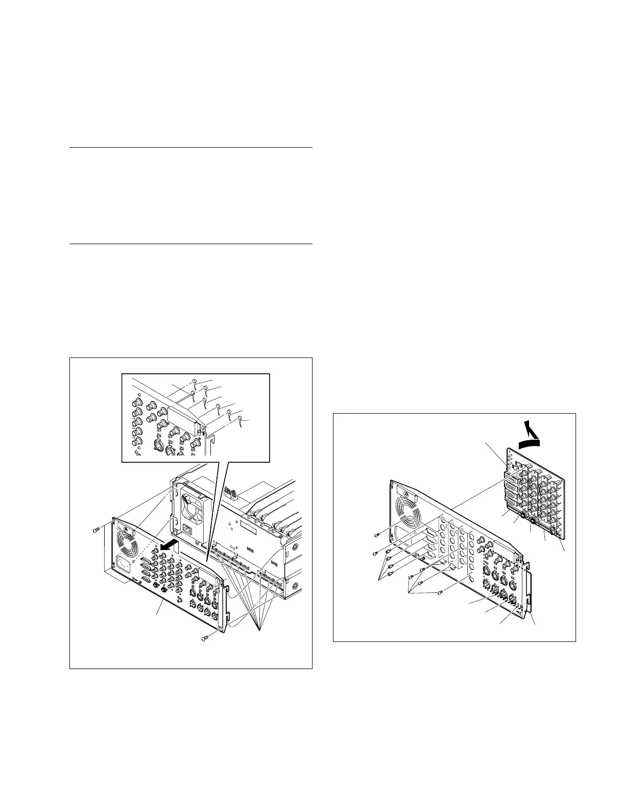
Removal/Reattachment of the CP-341 board
(1) Remove the top panel. (Refer to Section 3-3.)
(2) Remove the seven connectors (blue, yellow, orange,
green, red, black, and white) on the rear panel with
tweezers.
(3) Remove the five screws (BVTT3 x 6) and remove the
rear panel in the arrow direction.
(4) Remove the fifteen screws (BVTP3 x 8) and eight
screws for connector and detach the CP-341 board by
opening the board in the arrow direction.
n
Use care not to break the terminals of capacitors, etc.
when removing the CP-341 board.
(5) Set the CP-341 board in the reverse direction of the
arrow and fix temporally it to the rear panel with the
fifteen screws.
(6) Apply a half-drop size of screw-locking compound to
each screw for connector, and tighten securely the
eight screws for connector together with the fifteen
screws.
(7) Reconnect the seven connectors disconnected in Step 2
with tweezers, using care to set the right color in the
right place.
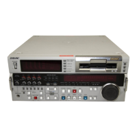
(8) Reattach the rear panel to the unit by connecting
securely the five connectors of the CP-341 board
(CN601, CN602, CN603, CN604, and CN605) and the
three connectors of the CP-342 board (CN606, CN607,
and CN608) to the eight connectors of the MB-859
board.
(9) Fix the rear panel with the unit with the five screws.
3-5. Removal/Reattachment of the Boards