— 4 —
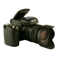
DSC-R1_L2
TABLE OF CONTENTS
1. SERVICE NOTE
1-1. Description on Self-diagnosis Display ····························1-1
1-2. Precaution on Replacing the SY-132 Board ····················1-2
1-3. Note when Replacing the Lens Block,
CMOS Block and Optical Filter Block ···························1-3
2. DISASSEMBLY
2-1. Disassembly·····································································2-3
2-2. The Method Of Attachment Of
PN-002 Flexible Board····················································2-5
2-3. How To Disassemble BT Lid ··········································2-7
2-4. The Method Of Attachment Of BK-002 Board
and Control (Mode) Switch Block ··································2-7
3. BLOCK DIAGRAMS
3-1. Overall Block Diagram (1/3)···········································3-1
3-2. Overall Block Diagram (2/3)···········································3-3
3-3. Overall Block Diagram (3/3)···········································3-5
3-4. Power Block Diagram (1/3)·············································3-7
3-5. Power Block Diagram (2/3)·············································3-9
3-6. Power Block Diagram (3/3)···········································3-11
4. PRINTED WIRING BOARDS AND
SCHEMATIC DIAGRAMS
4-1. Frame Schematic Diagram ··············································4-1
4-2. Schematic Diagrams ························································4-5
4-3. Printed Wiring Boards ···················································4-43
4-4. Waveforms·····································································4-69
4-5. Mounted Parts Location ················································4-74
5. REPAIR PARTS LIST
5-1. Exploded Views ·······························································5-2
5-2. Electrical Parts List ·························································5-9
Section Title Page Section Title Page

 Loading...


