6-7
DSC-T20/T25_ADJ
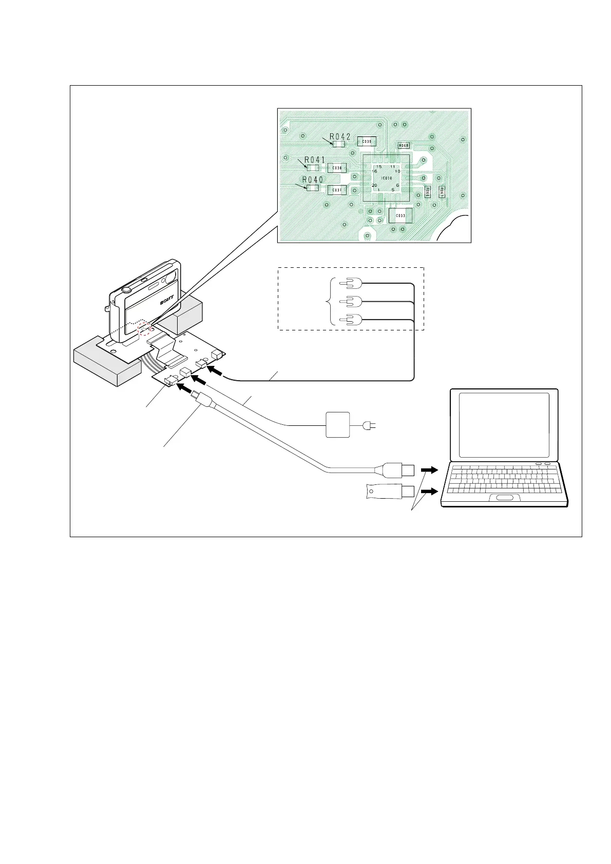
Fig. 6-1-5
Note: For the USB connection, refer to “4. HD Station Modifying Procedure”.
P
b
P
r
Y
PC
OS: Windows 98/98SE/Me/2000/XP
RAM: 256MB or more recommended
USB: 2.0 recommended
(also compatible with 1.1)
Two connectors are required.
AC IN
AC power adaptor
USB cable
(1-829-868-41)
USB connector
HASP Key
To DC IN jack
To USB
connector
To USB
connector
Terminated
75 Ω
Pr (Red)
Pb (Blue)
Y (Green)
(COMPONENT OUT)
Measurement Point (Component out (Y, Pb, Pr) level adj.)
To COMPONENT OUT
• Connection diagram when “Component out (Y, Pb, Pr) level adjustment” in “Video System Adjustment” is performed.





 To Next Page