EasyManua.ls Logo

Sony DTC-1000ES Service Manual

Sony DTC-1000ES
96 pages
To Next Page IconTo Next Page
Page #1 background imageLoading...
Page #1 background image
SERI|ICE
MANUAL
at,
:Ér.\
AEP Mdel
UK
Model
System
Tape
Recording system
Recording time
Tape speed
Drum
rotation
Error correction
Number of channel
D/A
conversion
Frequency
response
Signal to
noise
ratio
Dynamic
range
Total harmonic distortion
Wow and
flutter
InDut
Oigital audio
tape
recorder
Digital audio
tape
Rotary head.
minutes
(with
DT-120)
8.15
mm,|s
Approx. 2,000
rpm
Double
Reed Solomon code
2 channels.
stereo
1ôbit linear
2-22,W
Hz
*0.5
dB
More than 92 dB
More
than
90 dB
Less than 0.0055%
Below
measurable limit
SPECIFICATIONS
General
Power requirements
Power consumption
Dimensions
Power
requirements
Dimensions
Weight
220V AC,50/60H2
(AEP
model)
24OV AC,50Hz
(UK
model)
48W
Approx.
470x10ox42Q mm
(w/h/d)
(18t/,
x 3ts/r6x
1
6
t/,
inches)
incl.
side
wood
Approx.
430 x
100
x 420 mm
(w/h/d)
(16r/r,
x 3r5l,. x 16% inches)
excl.
side
wood
Approx.
12 kg
(m
lb
7
oz)
incl.
side
wood
3
V DC, with
R6
(size
AA)
batteries
Approx.
67
x
175
x 18
mm
(w/h/d)
(2s/"x
6'
/rx
n
/r.
inches)
Approx. 145
g
(5
oz)
incl. batteries
Weight
Supplled
accessorles
Remote commander
(1)
.--..RM-R1
Sony batteries SUM-3
(NS)
(2)
Audio connecting
cords
(2
phono
plugsx2
phono plugs,
stereo,
for
line inputs
and
outputs)
(2)
Screws to
secure the cabinet
(4)*
Remote
commander
(supplied).....RM-R1
Remote control system
Infrared
control
Tape
Track
pitch
Sampting
lrequency
Modulation system
Transter
rate
13.6
gm
(20.4
yml
48 kHz,
44.1
kHz, 32 kHz
8-10
Modulation
2.46
Mbit/sec.
(before
modulation)
*
The side wood
panels
on both sides of the deck are
detachable.
After
removing the
screws, secure the
cabin€fi
with the supplied
lock screws
(tour
M4x6).
For safety, before doing this, be sure
to disconnect
the
AC
power
cord
from the AC
outlet.
DIGITAL
AUDIO TAPE
DECK
Input
jacks
Jack
type
lmpedance
Ratecl input
level
LINE
IN
DIGITAL
Phono
Phono
50
kohms
75 ohms
-10
dBs
0.5
Vp-p
Output
iacks
Jack type
lmpedance
Rated output
Load
impedance
LINE OUT
HEAD.
PHONES
DIGITAL
OUT
Phono
Stereo
phone
Phono
470
ohms
150
ohms
75 ohms
-
10
dBs
0-28
mW
0.5
Vp-p
More
than
10 kohms
32 ohms
75
ohms
SONY
Question and Answer IconNeed help?

Do you have a question about the Sony DTC-1000ES and is the answer not in the manual?

Sony DTC-1000ES Specifications

General IconGeneral
BrandSony
ModelDTC-1000ES
CategoryTape Deck
LanguageEnglish

Summary

SPECIFICATIONS

General Specifications

Covers power requirements, consumption, and physical dimensions of the unit.

Input/Output and Tape Specifications

Details on connectivity, impedance, signal levels, and tape characteristics.

Supplied Accessories

List of items included with the DTC-1000ES when purchased.

Safety and Repair Guidelines

Safety-Related Component Warning

Identifies critical components for safe operation and replacement.

Flexible Circuit Board Repairing Guidelines

Precautions for soldering and handling flexible circuit boards during repairs.

Chip Component Replacement Precautions

Advice on handling and replacing chip components to prevent damage.

SECTION 1 OUTLINE

Front Panel Controls and Indicators

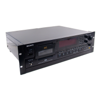
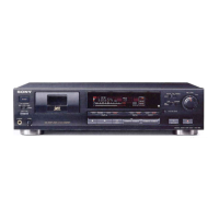
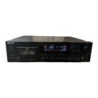
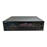
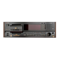
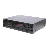
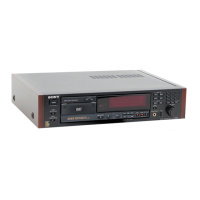
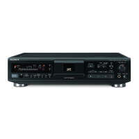
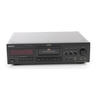
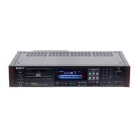
Detailed description of all buttons, switches, jacks, and display indicators on the front panel.

DTC-1000ES Test Mode Operation

Test Mode Operation and Display

Explains how to enter test modes and interpret the counter display for diagnostic purposes.

SECTION 2 BLOCK DIAGRAM

Audio, Microcomputer, and Servo Blocks

High-level schematic showing major functional blocks and their interconnections.

SECTION 3 DISASSEMBLY

Outer Casing and Main Board Removal

Steps for disassembling the outer casing and removing main internal boards.

Component Board and Mechanical Unit Disassembly

Procedures for detaching internal boards like Analog, MD Servo, and mechanical sub-assemblies.

SECTION 4 ADJUSTMENTS

4-1. MECHANICAL ADJUSTMENT

Detailed steps for adjusting the tape path and guides for optimal performance in FWD mode.

4-2. ELECTRICAL ADJUSTMENT

Procedures for calibrating various electrical parameters like torque, voltage, and speed.

SECTION 5 DIAGRAMS

Semiconductor Location

Guide to the physical placement of semiconductors on circuit boards.

5-1. Mounting Diagram (MD Servo & Digital Blocks)

Illustrates component placement on MD Servo and Digital boards.

5-2. Schematic Diagram (MD Servo Block)

Detailed circuit diagram for the MD Servo system.

5-3. Mounting Diagram (Power Block)

Shows the physical layout of components on the Power Block.

5-4. Schematic Diagram (Power Block)

Electrical schematic of the power supply circuitry.

5-4. Schematic Diagram (Digital Block)

Circuit diagram for digital signal processing and control logic.

5-6. Schematic Diagram (Analog & Microcomputer Block)

Circuit schematics for the analog signal path and microcomputer interface.

SECTION 6 EXPLODED VIEWS AND PARTS LIST

Outer Casing Exploded View and Parts

Illustration and list of parts for the outer casing assembly.

Front Panel Exploded View and Parts

Shows the front panel assembly and lists all related components and their part numbers.

Servo Mechanism Block Exploded View and Parts

Detailed breakdown of the servo mechanism with parts list.

Cassette Table Block Exploded Views and Parts

Illustration and list of parts for the cassette table mechanism.

SECTION 7 ELECTRICAL PARTS LIST

Capacitors and Resistors

Lists capacitors and resistors with part numbers, values, and tolerances.

Semiconductors

Details semiconductor components like diodes and transistors with part numbers.

Integrated Circuits (ICs)

Lists integrated circuits with part numbers, manufacturers, and types.

Connectors and Other Components

Lists various connectors, switches, motors, and crystals with their part numbers.

Related product manuals