RMT-D165A/RMT-D165P/RMT-D166P
SERVICE MANUAL
CD/DVD PLAYER
System
Laser: Semiconductor laser
Signal format system: NTSC
Audio characteristics
Frequency response: DVD VIDEO (PCM
96 kHz): 2 Hz to 44 kHz (±1.0 dB)/
DVD VIDEO (PCM 48 kHz): 2 Hz to
22 kHz (±0.5 dB)/CD: 2 Hz to 20 kHz
(±0.5 dB)
Signal-to-noise ratio (S/N ratio): 115 dB
Harmonic distortion: 0.003%
Dynamic range: DVD VIDEO: 103 dB/
CD: 99 dB
Wow and flutter: Less than detected value
(±0.001% W PEAK)
Outputs
(Jack name: Jack type/Output level/
Load impedance)
LINE OUT (AUDIO): Phono jack/
2 Vrms/ 10 kilohms
DIGITAL OUT (COAXIAL): Phono jack/
0.5 Vp-p/75 ohms
COMPONENT VIDEO OUT
(Y, PB, PR): Phono jack/Y: 1.0 Vp-p/
PB, PR: 0.65 Vp-p/75 ohms
LINE OUT (VIDEO): Phono jack/
1.0 Vp-p 75 ohms
S VIDEO OUT: 4-pin mini DIN/Y:
1.0 Vp-p, C: 0.286 Vp-p/75 ohms
General
Power requirements:
120 V AC, 60 Hz
110-240 V AC, 50/60 Hz
See page 5 for further information
Power consumption: 11 W
Dimensions (approx.): 430 × 43 ×
237.7 mm (17 × 2
11
/16 × 9
1
/2 in.)
(width/height/depth) incl. projecting
parts
Mass (approx.): 1.95 kg (4
1
/3 lb)
Operating temperature: 5°C to 35°C
(41°F to 95°F)
Operating humidity: 25% to 80%
SPECIFICATIONS
Supplied accessories
See page 17
Specifications and design are subject to
change without notice.
ENERGY STAR
is a U.S. registered
mark.
As an ENERGY STAR
Partner, Sony
Corporation has determined that this
product meets the ENERGY STA R
guidelines for energy efficiency.
Canada Model
PX Model
Mexico Model
Latin Model
Brazil Model
Hong Kong Model
GA Model
Taiwan Model
Korea Model
Saudi Arabia Model
Middle East Model
India Model
Australia Model
China Model
Argentina Model
US Model
Iran Model
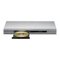
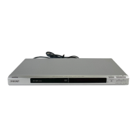
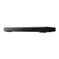
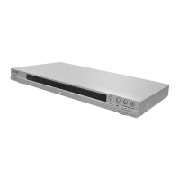
DVP-NS575P
DVP-NS355/NS501P/NS507P/NS525P/NS575P/NS585P
Notes: US and Canada model only
Photo : DVP-NS575P
RMT-D165P
Brazil Model
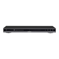
DVP-NS355
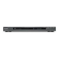
China Model
DVP-NS507P/NS525P/NS585P
Middle East Model
DVP-NS585P
US Model
DVP-NS501P