3-9
DXC-D35/D35WS(UC)
DXC-D35P/D35WSP(CE) V1
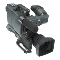
TP501
RV501
RV502
RV503
RV504
RV505
E501
FL502
CN501
1
2
3
4
5
6
A
B C
D
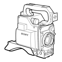
ES-32 board (A side) (DXC-D35/D35P)
ES-33 board (A side) (DXC-D35WS/D35WSP)
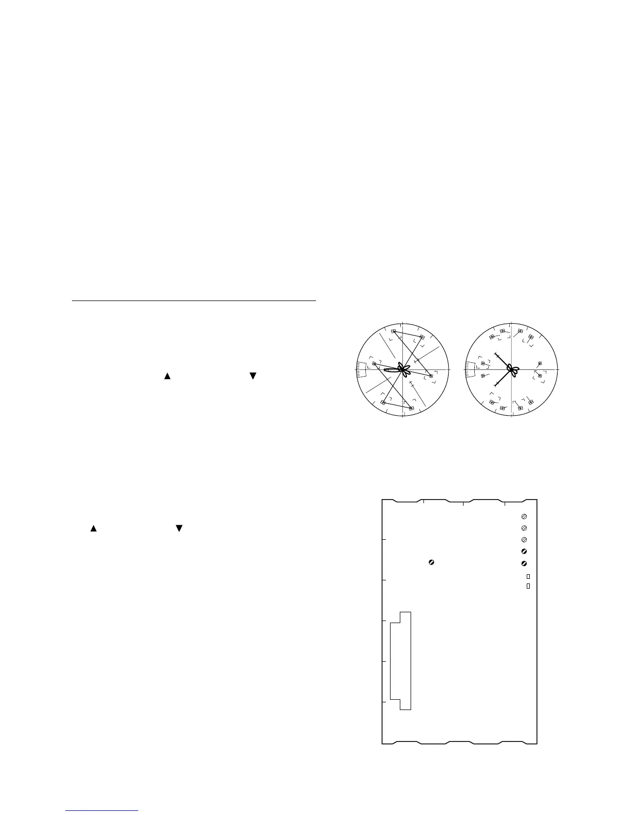
3-3-6. Chroma (VBS) Level Adjustment
n
Use the vectorscope conforming to setup “7.5 IRE”. (for
NTSC)
Equipment: Verctorscope
To be extended: ES-32 board (for DXC-D35/D35P)
ES-33 board
(for DXC-D35WS/D35WSP)
Preparation:
. GAIN switch/Verctorscope: 75 % CAL
. Adjust the PHASE control on the vectorscope so that
the burst spot is overlapped to the 75 % axis.
. OUTPUT/DL/DCC + switch: BARS
Test point: VIDEO OUT connector
Adjustment Procedure
1. [for NTSC]
SERVICE menu “PAGE 7”
→ B-Y BST
Adjust by the UP switch or DOWN switch so that
burst spot is located at 75 % scale mark on the vector-
scope screen.
(In case of NTSC, make sure that “R-Y BST” must be
“0”.)
[for PAL]
SERVICE menu “PAGE 7”
→ R-Y BST
B-Y BST
Adjust “R-Y BST” and “B-Y BST” alternately by UP
switch or DOWN switch so that burst spot is
located at 75 % scale mark on the vectorscope screen.
2. Adjust the adjusting volume controls below to enter
the beam spot of each color within the area “4”
specified for each color on the vectorscope screen.
1 RV503 (B-Y LEV)
/ES-32 board (DXC-D35/D35P)
/ES-33 board (DXC-D35WS/D35WSP)
1 FL502 (PHASE)
/ES-32 board (DXC-D35/D35P)
/ES-33 board (DXC-D35WS/D35WSP)
1 RV504 (CHROAMA VBS LEV)
/ES-32 board (DXC-D35/D35P)
/ES-33 board (DXC-D35WS/D35WSP)
3. Then, perform above procedure item 1 again
[for NTSC] [for PAL]
R
M
G
CY
G
Y
L
B
R
M
G
CY
G
Y
L
B
100%
75%
3-3. Camera Adjustment