10
3. Procedure
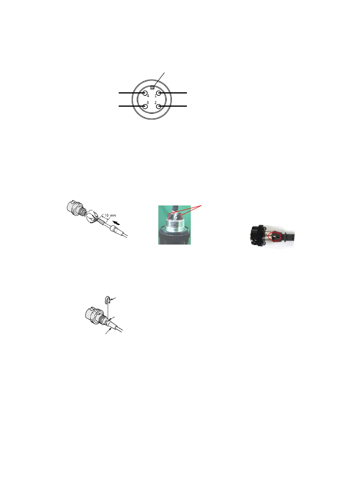
3-1. Wiring to the connector
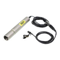
Connect the wore of the AMPLIFIER CASE ASSY to the CONNECTOR (PLUG). (Fig. 7)
3-2. Attaching the microphone bushing
Apply the adhesive agent (Locktite (Prism 403) or equivalent) between the edge of the coating of
the microphone cable and the point about 10mm from the edge (Fig. 8), and the side of heat
shrinkable tube (Fig. 9), then, attach microphone bushing.
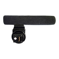
At that time, the cut of the microphone bushing would be by the side of #4pin. (shown in red circle
of Fig. 10)
3-3. Attaching the cord clamp
Put the cord clamp in the groove of the microphone bushing as shown in the Fig. 11 and caulk it.
Shield wire
Shield wire
Apply the adhesive agent to
whole circumference of the
microphone cable between the
edge of the coating and the point
about 10mm from the edge.
Microphone bushing
Apply the adhesive agent to the side
of the heat shrinkable tubes also.