13
3. Procedure
3-1. Wiring to the connector
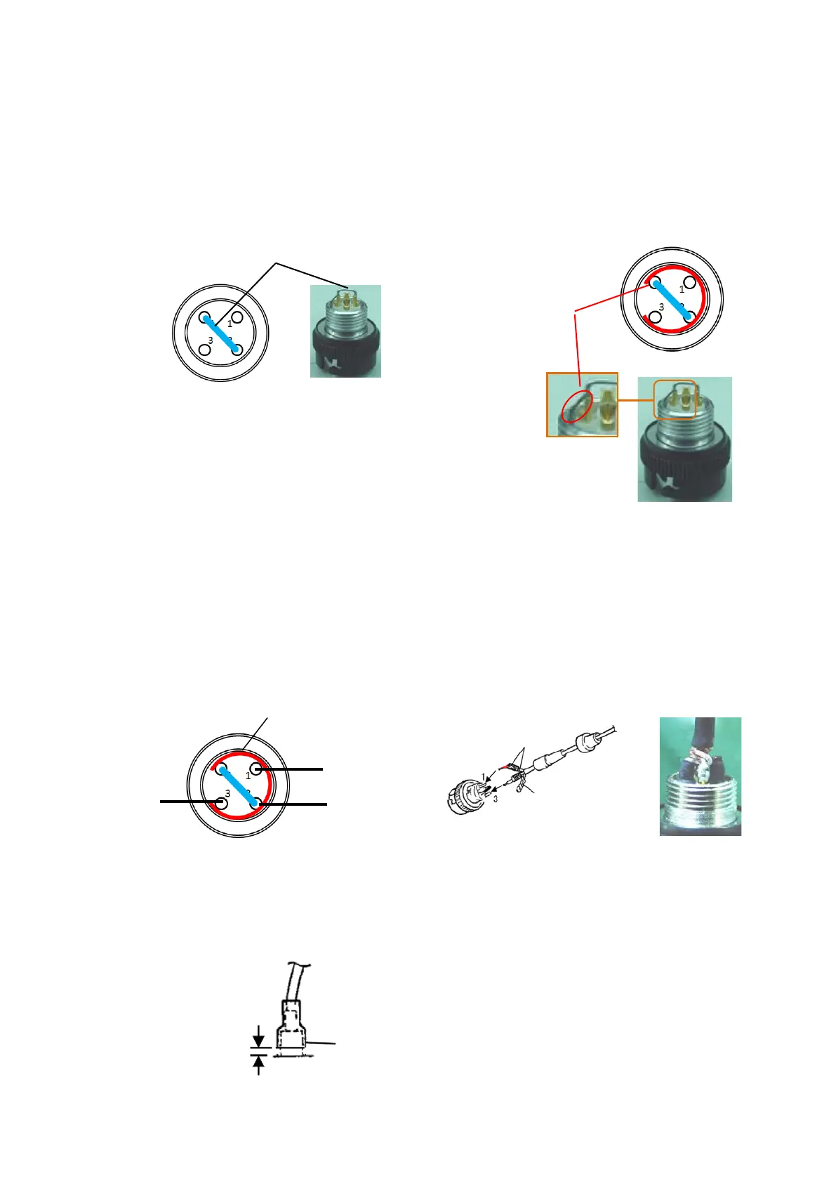
1) Attaching the jumper wire
Connect between #2pin and #4pin by jumper wire.
Reuse the jumper wire which is used originally.
(Do not solder it at this moment.) (Fig. 19)
2) Attaching the ground ring (only for improved one for high frequency
interference.)
Attach the ground ring as shown in the figure. (Fig. 20)
3) Solder the jumper wire and the ground ring to the connector.
As for the ground ring, solder its tip to the #4pin.
4) Connect the wire of the amplifier case Assy to the connector (plug). (Fig. 21)
Bundle two shield wires and solder it to #4pin. (Fig. 22 and Fig. 23)
5) Cover the heat shrinkable tubes on the terminals (#1pin and #3pin) and heat them to shrink by
dryer or equivalent. (Fig. 24)
4
Shield wire
Ground ring
Float it