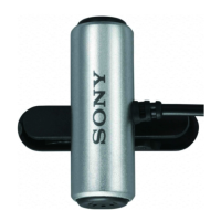
ECM-TS125
AEP Model
SERVICE MANUAL
ELECTRET CONDENSER MICROPHONE
MICROFILM
SPECIFICATIONS
SECTION 1
GENERAL
This section is extracted
from instruction manual.
— 2 —
1. Check the area of your repair for unsoldered or poorly-soldered
connections. Check the entire board surface for solder splashes
and bridges.
2. Check the interboard wiring to ensure that no wires are
"pinched" or contact high-wattage resistors.
3. Look for unauthorized replacement parts, particularly
transistors, that were installed during a previous repair. Point
them out to the customer and recommend their replacement.
4. Look for parts which, through functioning, show obvious signs
of deterioration. Point them out to the customer and
recommend their replacement.
5. Check the B+ voltage to see it is at the values specified.
6. Flexible Circuit Board Repairing
• Keep the temperature of the soldering iron around 270˚C
during repairing.
• Do not touch the soldering iron on the same conductor of the
circuit board (within 3 times).
• Be careful not to apply force on the conductor when soldering
or unsoldering.
SAFETY CHECK-OUT
After correcting the original service problem, perform the following
safety checks before releasing the set to the customer.
Type Electret condenser microphone
Dimensions Microphone parts:
11 × 26 mm (diameter/length)(
7
/16 × 1
1
/16 in.)
Battery box parts:
40 × 16.5 × 46 mm (w/h/d)
(1
5
/8 × 2
1
/32 × 1
13
/16 in.)
Mass Microphone parts (including cord):
Approx. 15 g (0.53 oz.)
Battery box parts
(including lithium battery and cord):
Approx. 17 g (0.6 oz.)
Cord Microphone parts:
∅2.2 mm (
3
/32 in.)OFC litz cord (2 core shielded)
Length: approx. 1 m (39
3
/8 in.)
Battery box parts:
∅2.2 mm (
3
/32 in.)OFC litz cord (2 core shielded)
Length: approx. 0.3 m (11
7
/8 in.)
Supplied accessories
Battery box (1)
Holder clip (1)
Frequently response
100 – 16,000 Hz
Directivity Unidirectional × 2
Output impedance
3 kΩ ±30%
Sensitivity Open circuit output voltage level -42 ±4dB
0 dB=1V/Pa, 1,000 Hz(1Pa=10µ bar=94 dBSPL)
Battery life Approx. 100 hours
(with Sony lithium battery CR2025(not supplied))
Maximum sound pressure input level
Approx. 110 dBSPL
1% wave distortion at 1,000 Hz
(0 dBSPL=2 × 10
-5
Pa)
Operating temperature range
0°C – 40°C (32°F – 104°F)
Design and specifications are subject to change without notice.
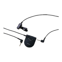
1 POWER switch
2 Battery check indicator
When you turn the power on, the battery check indicator lights up
momentarily. This is normal. The light tells you that the battery still
has life. When the battery becomes weak, the indicator lights
dimly or does not light at all.
3 L-shaped stereo miniplug (gold plated)
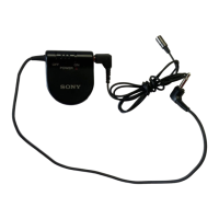
4 Battery box
You can clip the battery box to your tie, lapel or pocket.
5 Microphone jack
6 L-shaped stereo miniplug (gold plated)
7 Battery compartment
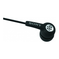
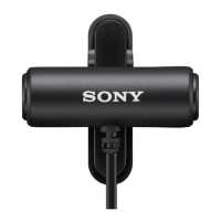
8 Microphone
9 Holder clip
A Interlock the projection of the holder to the groove on the
microphone.
B This microphone holder allows you to tilt the microphone 45°
backward or forward.
Ver 1.0 1999. 05