– 7 –
MEASUREMENT
POSITION
ADJUSTMENT
LOCATION
ILLUSTRATION AND SHAPE
AND NUMBER
ADJUSTMENT ITEM AND PROCEDURE
EQUIPMENT
AND SIGNAL
CHANNEL DISPLAY POSITION ADJUSTMENT
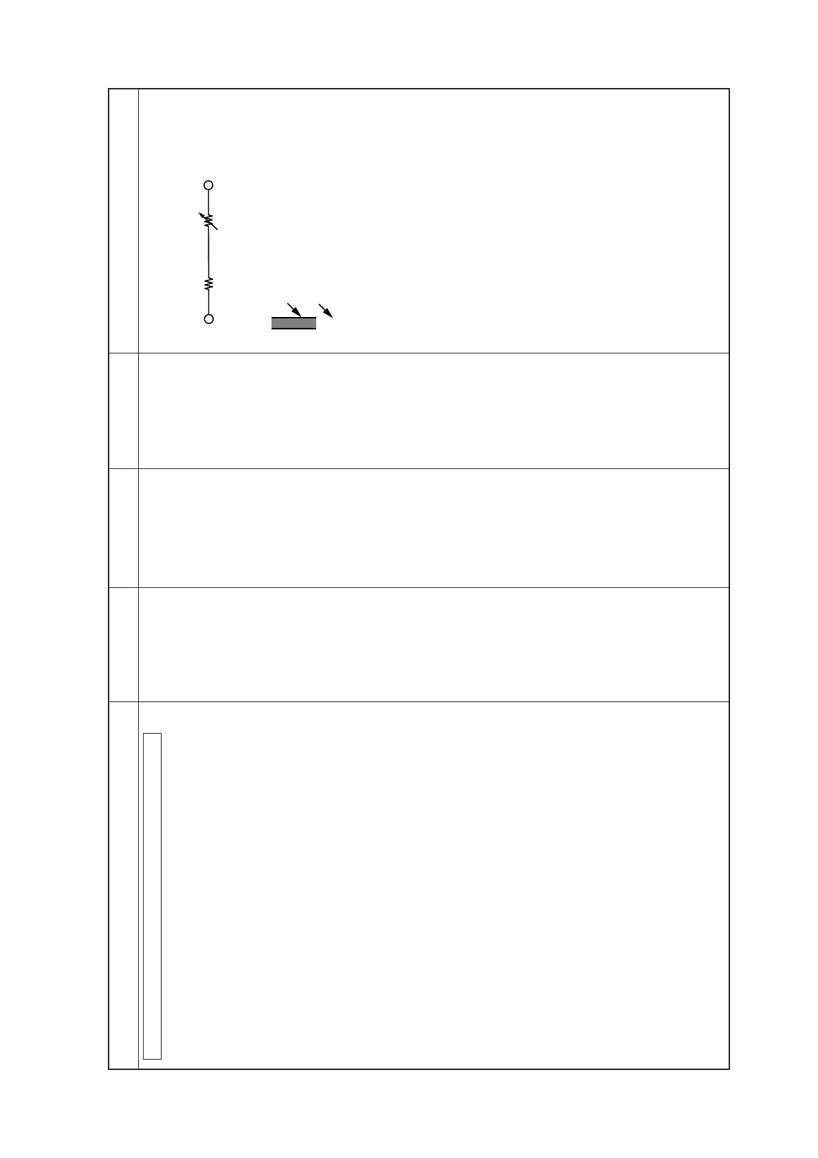
1. Insert variable resister (47 kΩ) and resister (15 kΩ) between
JL06 and JL61. (Fig 1.)
2. Short circuitry between JL04 and JL60 (GND).
3. Power switch in I.
4. Recieve 21CH then adjust channel No. display position by *RV
to be in the *Specification.
5. Recieve 68CH then adjust channel No. display position by *RV
to be in the *specification.
6. Repeat the procedures 9 and 10 in a few times to be in the
specification for both of 21CH and 68CH.
7. Recieve 40CH then check and confirm position of the display
bar in the specification.
8. Release the variable resister and resister out and open the short
circuitry between JL04 and JL60.
S601
*RV003
*RV001
*Channel No. and display bar are to be in line.
*Channel No. and display bar are to be in line.
JL06(CS) JL61(4.5V)
Fig 1.
Fig 2.
Display bar
Channel No.
21
15kΩ
47kΩ
*