30
b Notes
• Disconnect the i.LINK cable before changing [HDV/DV SEL] and [i.LINK CONV] settings. Otherwise,
the VCR may not recognize the video signal from the connected device.
• This VCR has a 4-pin i.LINK terminal. Select a cable that fits the terminal on the device to be connected.
z Tips
• When you use an i.LINK cable, the video and sound signals are transmitted digitally, producing high
quality pictures.
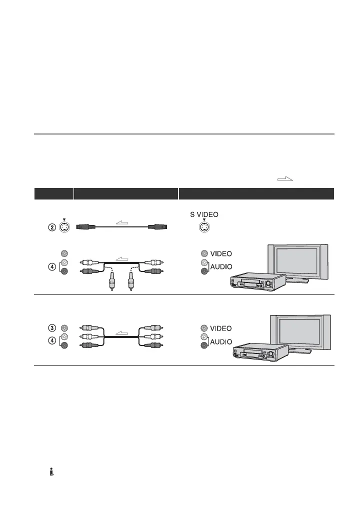
Using an S VIDEO cable and A/V connecting cable, or an A/V connecting cable
alone
* When connecting the VCR to a monaural device, connect the yellow plug of the A/V connecting cable to
the video jack on the device, and connect the white (left channel) or red (right channel) plug to the audio
jack on the device.
b Notes
• Select a cable that fits the terminal on the device to be connected.
z Tips
• When you connect the VCR to an external device via the S VIDEO jack by using an S VIDEO cable
(optional), higher quality DV format pictures can be produced than when using an A/V connecting cable.
When you connect with an S VIDEO cable (optional) alone, audio will not be output.
• If you connect the VCR to a TV using more than one type of cable to input pictures from a jack other than
the HDV/DV (i.LINK) interface, the order of priority of the input signal is as follows:
S VIDEO IN t VIDEO IN
: Signal flow
VCR Cable External device
S VIDEO cable (optional) AV device with S VIDEO jack
t SD quality
(Red)
(White)
(Yellow)
A/V connecting cable (optional)
A/V connecting cable (optional)
AV device with audio/video jacks*
t SD quality
(White)
(Yellow)
(Red)
Recording the picture from TV, VCR, etc. (Continued)