Do you have a question about the Sony HCD-EC99 and is the answer not in the manual?
| Brand | Sony |
|---|---|
| Model | HCD-EC99 |
| Category | Car Receiver |
| Language | English |
Notes on handling and replacing chip components, especially tantalum capacitors.
Guidelines for repairing flexible circuit boards, including soldering temperature.
Precautions for handling the optical pick-up block to prevent electrostatic discharge.
Instructions for safely checking laser diode emission from the optical pick-up block.
Characteristics and handling of unleaded solder, including melting point and viscosity.
Step-by-step instructions to unlock the disc tray for demonstration purposes.
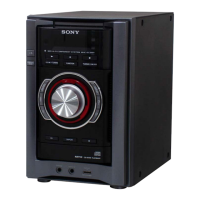
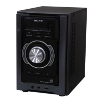
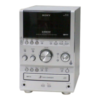
Identifies and describes the buttons and ports on the main unit of the system.
Instructions for setting the system's clock using the remote control.
A flowchart illustrating the sequence of disassembly steps for the unit.
Detailed instructions and diagrams for removing the left and right side panels.
Instructions for removing the top panel, including release of front claws.
Steps and diagrams for accessing and removing the main board assembly.
Procedure for removing the front panel assembly, including CD tray access.
Instructions for disassembling and removing the back panel block.
Steps to remove the CD mechanism block, including flexible flat cables.
Procedure for disassembling the base unit, including springs and insulators.
Instructions for removing the optical base assembly, including flexible flat cables.
Procedure for accessing and replacing the belt in the CD mechanism.
Procedure to reset the system to initial conditions, clearing stored data.
How to enter Panel Test Mode to check LEDs and LCD segments.
How to display the firmware version and model information in Panel Test Mode.
Procedure to test all buttons and the volume dial in the Panel Test Mode.
Enables CD playback repeat for limitless times, overriding the 5-time limit.
Mode to lock the CD tray for anti-theft purposes in shops.
Mode to switch the CD power supply on/off, holding the state even if unplugged.
How to switch between 9 kHz and 10 kHz AM tuning intervals.
Mode to optionally move the CD sled motor, useful for cleaning the optical pick-up.
Procedure combining CD Ship Mode with a cold reset function.
Checks optical pick-up system servo operations, including S-Curve and Error Rate modes.
Allows SLED movement and optical pick-up laser power control.
How to display and trace CDM and BD error codes for troubleshooting.
Mode for checking various CD operations like RF gain and tracking servo settings.
Notes and checks for the CD section, including focus bias check.
Procedure to check the focus bias using an oscilloscope for the CD board.
Location and settings for tuner section adjustments.
Procedure to confirm AM frequency coverage using a digital voltmeter.
Adjustment for maximum reading on the level meter for AM tracking.
Adjustment of FM frequency coverage using a digital voltmeter.
Adjustment for a minimum reading on the level meter for FM tracking.
Procedure to adjust the FM detector for optimal performance.
Checks if automatic scanning stops correctly when receiving FM signals.
Block diagram showing the signal paths for the CD player and tuner sections.
Block diagram illustrating the main functional blocks and signal flow.
Block diagram showing the panel controls and power supply circuitry.
Layout of components and traces on the CD board's component and conductor sides.
Detailed schematic of the CD board, showing component interconnections.
Component and trace layout for the USB board's component and conductor sides.
Detailed schematic of the USB board, showing circuit connections.
First part of the main board schematic, detailing circuit connections.
Second part of the main board schematic, detailing circuit connections.
Component layout for the main board, showing semiconductor and connector locations.
Layouts for the 2CH-4CH and 3CH amplifier board printed wiring.
Schematic diagram for the 2-channel to 4-channel amplifier board.
Schematic diagram for the 3-channel amplifier board (EC99 model).
Component layout for the panel board, showing switch and display connections.
Detailed schematic of the panel board, including system controller connections.
Layouts for the audio input/output, key, and power supply boards.
Schematics for audio, key, and power supply sections.
Block diagrams illustrating the internal structure of key integrated circuits.
Detailed pin functions for the CD-MP3 processor IC on the CD board.
Detailed pin functions for the USB controller IC on the USB board.
Detailed pin functions for the system controller IC on the panel board.
Exploded view of the unit's front panel, side panels, and chassis section.
Detailed exploded view of the front panel components, knobs, and plates.
Exploded view of the main chassis, including back panels and CD mechanism.
Exploded view of the main unit's internal structure, showing boards and transformers.
Exploded view of the CD mechanism assembly, detailing motors and components.
List of electrical components for the 2-channel to 4-channel amplifier board.
List of electrical components for the 3-channel amplifier board (EC99).
List of electrical components for the CD board.
Component lists for Panel, PT-Switch, REG, and USB boards.
Component lists for the Key and Main boards.
Detailed list of resistors and capacitors for the Main board.
List of diodes, transistors, and coils for the Main board.
Continuation of the Main board resistor list, covering various types.
Further continuation of the Main board resistor list.
Component lists for Main and Panel boards, including switches and transformers.
Detailed list of capacitors, diodes, transistors, and connectors for the Panel board.
Component list for the PT-Single board, including resistors, switches, and vibrator.
Component lists for PT-Switch, REG, and USB boards, including ICs and connectors.
List of miscellaneous parts like cables, fans, transformers, and accessories.