EasyManua.ls Logo

Sony HCD-FR10W User Manual

Sony HCD-FR10W
140 pages
To Next Page IconTo Next Page
Page #1 background imageLoading...
Page #1 background image
SERVICE MANUAL
Sony Corporation
Audio Group
Published by Sony Engineering Corporation
US Model
Canadian Model
SACD/DVD RECEIVER
9-879-099-03
2004L16-1
© 2004.12
Ver. 1.2 2004. 12
SPECIFICATIONS
HCD-FR10W
HCD-FR10W is the amplifier, DVD/SACD
and tuner section in DAV-FR10W.
Model Name Using Similar Mechanism HCD-FR1
Mechanism Type CDM69-DVBU16
Optical Pick-up Name DBU-1
AUDIO POWER SPECIFICATIONS POWER
OUTPUT AND TOTAL HARMONIC
DISTORTION:
With 4 ohm loads, both channels driven, from 20 –
20,000 Hz; rated 75 watts per channel minimum RMS
power, with no more than 0.7 % total harmonic
distortion. (from 250 milli watts to rated output)
×
Amplifier section
Surround mode Front:
114
W +
114
W
(reference) (with SS-TS21)
music power output Center*:
114
W
(with SS-CT33)
Surround*:
114
W +
114
W
(with SA-TS22W, SS-TS21)
Subwoofer*:
115
W 2
(with SS-WS12)
*Depending on the sound field settings and the source,
there may be no sound output.
Inputs VIDEO/SAT:
Sensitivity: 250 mV/
450 mV
Impedance: 50 kilohms
Output SURROUND BACK
Voltage: 2V
Impedance: 1 kilohms
Phones Accepts low-and high-
impedance headphones.
Super Audio CD/DVD system
Laser Semiconductor laser
(Super Audio CD/DVD:
= 650 nm)
(CD: λ
λ
= 780 nm)
Emission duration:
continuous
Signal format system NTSC
Frequency response (at 2 CH STEREO mode)
DVD (PCM): 2 Hz to 22
kHz (±1.0 dB)
CD: 2 Hz to 20 kHz (±1.0
dB)
Harmonic distortion Less than 0.03 %
Tuner section
System PLL quartz-locked digital
synthesizer system
FM tuner section
Tuning range 87.5 – 108.0 MHz
(100 kHz step)
Antenna (aerial) FM wire antenna (aerial)
Antenna (aerial) terminals
75 ohms, unbalanced
Intermediate frequency 10.7 MHz
AM tuner section
Tuning range 531 – 1,710 kHz (with the
interval set at 9 kHz)
530 – 1,710 kHz (with the
interval set at 10 kHz)
Video section
Outputs
General
Power requirements
Power consumption
Dimensions (approx.)
Mass (approx.)
Antenna (aerial)
Intermediate frequency
AM loop antenna (aerial)
450 kHz
Video: 1 Vp-p 75 ohms\
S VIDEO:
Y: 1 Vp-p 75 ohms
C: 0.286 Vp-p 75 ohms
COMPONENT:
Y: 1 Vp-p 75 ohms
P
B
/C
B
, P
R
/C
R
: 0.65 Vp-p
75 ohms
××
120 V AC, 60 Hz
90 W
430 × 70 × 398 mm
(17 2
7
/8 15
3
/4 inches)
(w/h/d) incl. projecting
parts
5.5 kg (12 lb 12 oz)
Design and specifications are subject to change
without notice.
w
w
w
.
x
i
a
o
y
u
1
6
3
.
c
o
m
Q
Q
3
7
6
3
1
5
1
5
0
9
9
2
8
9
4
2
9
8
T
E
L
1
3
9
4
2
2
9
6
5
1
3
9
9
2
8
9
4
2
9
8
0
5
1
5
1
3
6
7
3
Q
Q
TEL 13942296513 QQ 376315150 892498299
http://www.xiaoyu163.com

Table of Contents

Question and Answer IconNeed help?

Do you have a question about the Sony HCD-FR10W and is the answer not in the manual?

Sony HCD-FR10W Specifications

General IconGeneral
TypeMini Hi-Fi Component System
Number of Channels2
Tuner BandsFM, AM
CD PlayerYes
Remote ControlYes
Frequency Response20Hz - 20kHz
Speaker Impedance6 ohms
FunctionsAmplifier, CD, Tuner
Input Impedance47k ohms

Summary

SPECIFICATIONS

AUDIO POWER SPECIFICATIONS POWER OUTPUT AND TOTAL HARMONIC DISTORTION

Details power output and harmonic distortion for the amplifier section.

Super Audio CD/DVD system

Specifies laser type, emission duration, and frequency response for SACD/DVD.

General

Covers power requirements, consumption, dimensions, and mass.

SERVICING NOTE

GENERAL

Front Panel Controls

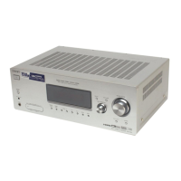
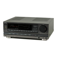
Identifies buttons, indicators, display, and jacks on the front panel.

Rear Panel Connections

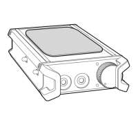
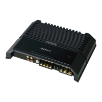
Lists all input and output terminals on the rear panel.

DISASSEMBLY

3-1. FLOW CHART

Outlines the sequential steps for disassembling the unit.

3-4. MECHANISM DECK (CDM69-DVBU16)

Explains how to remove the mechanism deck assembly.

ASSEMBLY

TEST MODE

Cold Reset

How to reset the unit to factory default settings.

CDM Ship Mode

Procedure to set the optical pick-up for shipping.

STARTING TEST MODE

Step-by-step guide to enter the test mode.

OPERATING TEST MODE: SYSCON DIAGNOSIS

How to perform system controller diagnosis and check menus.

1. DRIVE AUTO ADJUSTMENT

Guide for automatic servo adjustment for DVD, CD, and DVD-DL.

3. EMERGENCY HISTORY

Displays servo emergency history and clearing procedures.

ELECTRICAL ADJUSTMENT

AUTO SERVO ADJUSTMENT

Procedure for re-adjusting servo circuits after component replacement.

DIAT SIGNAL RF LEVEL ADJUSTMENT

Adjusts transmission distance of RF signal for DIAT communication.

DIAGRAMS

7-1. BLOCK DIAGRAM — RF/SERVO SECTION —

7-2. BLOCK DIAGRAM — AUDIO (DSP) SECTION —

7-8. SCHEMATIC DIAGRAM — RF BOARD —

7-25. SCHEMATIC DIAGRAM — AMP BOARD (1/4) —

7-26. SCHEMATIC DIAGRAM — AMP BOARD (2/4) —

7-27. SCHEMATIC DIAGRAM — AMP BOARD (3/4) —

7-28. SCHEMATIC DIAGRAM — AMP BOARD (4/4) —

Waveforms

– DMB08 Board Waveforms –

Shows typical waveforms from the DMB08 board.

• IC Block Diagrams

IC401 CXD3068Q Block Diagram

Block diagram for the CXD3068Q IC on the DMB08 board.

IC001 SP3723CAF0PM Block Diagram

Block diagram for the SP3723CAF0PM IC on the RF board.

• IC Pin Function Description

DMB08 BOARD IC206 ZIVA5X-C2F (DVD SYSTEM PROCESSOR) Pin Functions

Details the function of each pin for the IC206 processor.

DMB08 BOARD IC301 CXP973064-245R (MECHANISM CONTROLLER) Pin Functions

Pin function descriptions for the IC301 mechanism controller.

DMB08 BOARD IC607 CXD9618BQ (AUDIO DIGITAL SIGNAL PROCESSOR) Pin Functions

Pin functions for the IC607 audio digital signal processor.

DMB08 BOARD IC801 CXD2753R (DSD DECODER) Pin Functions

Pin functions for the IC801 DSD decoder.

EXPLODED VIEWS

8-1. CASE SECTION

Exploded view and parts list for the unit's case.

8-2. FRONT PANEL SECTION

Exploded view and parts list for the front panel assembly.

8-10. OPTICAL PICK-UP SECTION (DBU-1)

Exploded view and parts list for the optical pick-up section.

ELECTRICAL PARTS LIST

RESISTORS

List of all resistors used in the amplifier section.

CAPACITORS

List of all capacitors used in the amplifier section.

SEMICONDUCTORS

List of all semiconductors used in the amplifier section.

AMP Board Components

Detailed list of components for the AMP board.

DMB08 Board Capacitors

List of capacitors used in the DMB08 board.

DMB08 Board ICs

List of integrated circuits used on the DMB08 board.

DMB08 Board Transistors and Resistors

List of transistors and resistors for the DMB08 board.

DMB08 Board Components (Resistors)

List of resistors for the DMB08 board.

REVISION HISTORY

Revision History Table

Details changes made in different versions of the manual.

Related product manuals