Do you have a question about the Sony HCD-GT111 and is the answer not in the manual?
| Power Output | 100 W |
|---|---|
| Speaker Configuration | 2.0 |
| Speakers | 2 |
| CD Player | Yes |
| Number of Discs | 1 |
| FM/AM Tuner | Yes |
| Tuner Bands | FM, AM |
| Bluetooth | No |
| USB Playback | Yes |
| Audio Line In | Yes |
| Weight (Speaker) | 1.5 kg |
| Playable File Types | MP3 |
| Dimensions (Speaker) | 150 x 230 x 150 mm |
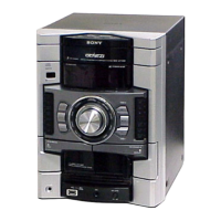
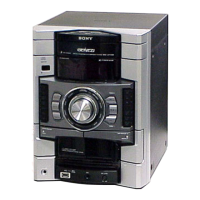
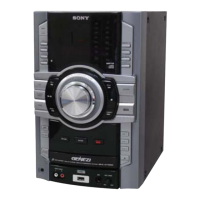
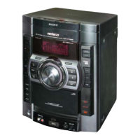
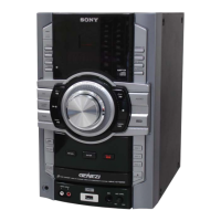
| Type | Mini Hi-Fi System |
Precautions for electrostatic discharge and handling the optical pick-up block and laser diode.
Characteristics of unleaded solder and procedure to release the disc tray lock.
Instructions for removing the tray and volume knob components.
Capacitor discharge for safety and service positions for boards.
Explanation of front and top view controls and their functions.
Step-by-step procedure for disassembling the unit.
Instructions for removing side, top, and back panel assemblies.
Steps to remove the tape mechanism deck from the unit.
Instructions for removing the front panel block assembly.
Steps for removing the main board assembly.
Procedure for removing the CD mechanism block assembly.
Procedure for replacing the belt (DLM3A) in the mechanism.
Checking LEDs, keys, model, and software versions.
Checking amplifier and tape sections in common test mode.
Clearing all data to initial conditions for customer return.
Switching the Variable Attenuation Control System ON/OFF.
Procedures for tuner step change, CD service, aging, error code, repeats, and ship modes.
General precautions before performing mechanical adjustments.
Specifications and procedures for torque measurement.
Specifications and procedures for tape tension measurement.
Adjusting head azimuth for optimal L-CH and R-CH output match.
Notes on CD block adjustments, test discs, and lens cleaning.
Confirming RF signal clarity and FM tune level.
Visual representation of CD servo and USB circuit interconnections.
Visual representation of the MAIN section circuit interconnections.
Detailed circuit diagram for the CD board.
Component layout and connections for the MAIN board.
Detailed circuit diagram for the MAIN board.
Detailed circuit diagram for the POWERAMP board.
Detailed circuit diagram for the DISPLAY board.
Detailed circuit diagram for the TRANS1 board.
Exploded view of the unit's case components.
Exploded view of the loading panel components.
Exploded view of the front panel components.
Exploded view of the top panel components.
Exploded view of the MAIN board components.
Exploded view of the CD mechanism components.
General information regarding parts list standardization and notations.
List of electrical components for the CD board.
List of electrical components for the DISPLAY board.
List of electrical components for the POWERAMP board.
List of electrical components for the TRANS1 board.
List of electrical components for the USB board.