SERVICE MANUAL
Sony Corporation
Audio&Video Business Group
Published by Sony Techno Create Corporation
HCD-GTZ4/GTZ4i/GTZ5
SPECIFICATIONS
COMPACT DISC RECEIVER
9-889-503-02
2009H05-1
©
2009.08
US Model
AEP Model
Australian Model
HCD-GTZ4i
E Model
HCD-GTZ4/GTZ5
Ver. 1.1 2009.08
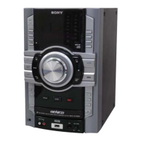
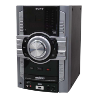
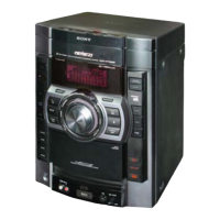
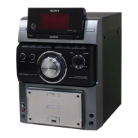
• HCD-GTZ4 is the amplifi er, USB, Disc player, tuner and
iPod section in MHC-GTZ4.
• HCD-GTZ4i is the amplifi er, USB, Disc player, tuner and
iPod section in LBT-GTZ4i, MHC-GTZ4i.
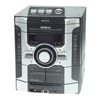
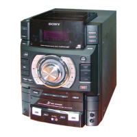
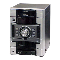
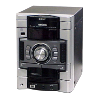
• HCD-GTZ5 is the amplifi er, USB, Disc player, tuner and
iPod section in MHC-GTZ5. Photo: HCD-GTZ5
Model Name Using Similar Mechanism NEW
Mechanism Type CDM88B-DVBU101
Optical Pick-up Block Name KHM-313CAB
“WALKMAN” and “WALKMAN”
logo are registered trademarks of
Sony Corporation.
MICROVAULT is a trademark of
Sony Corporation.
MPEG Layer-3 audio coding technol-
ogy and patents licensed from Fraun-
hofer IIS and Thomson.
Windows Media is a registered trade-
mark of Microsoft Corporation in the
United States and/or other countries.
“Memory Stick” is a trademark of
Sony Corporation.
iPod is a trademark of Apple Inc., reg-
istered in the U.S. and other countries.
USB section
Supported bit rate
MP3 (MPEG 1 Audio Layer-3):
32 – 320 kbps, VBR
WMA: 48 – 192 kbps
AAC: 48 – 320 kbps
Sampling frequencies
MP3 (MPEG 1 Audio Layer-3):
32/44.1/48 kHz
WMA: 44.1 kHz
AAC: 44.1 kHz
Transfer speed
Full-Speed
Supported USB device
Mass Storage Class
Maximum current
500 mA
Disc player section
System
Compact disc and digital audio system
Laser Diode Properties
Emission Duration: Continuous
Laser Output*: Less than 44.6 PW
* This output is the value measurement at a distance of
200 mm from the objective lens surface on the Optical
Pick-up Block with 7 mm aperture.
Frequency response
20 Hz – 20 kHz
Signal-to-noise ratio
More than 90 dB
Dynamic range
More than 88 dB
Amplifier section
HCD-GTZ5
Front speaker
Power output (rated): 110 W + 110 W
(at 6 :, 1 kHz, 1% THD)
RMS output power (reference):
200 W + 200 W (per channel at 6 :, 1 kHz, 10% THD)
Subwoofer
RMS output power (reference): 200 W
(at 6 :, 100 Hz, 10% THD)
HCD-GTZ4 / GTZ4i
The following are measured at
European model:
AC 230 V, 50 Hz
Other models:
AC 120, 220, 240 V, 50/60 Hz
Front speaker
Power output (rated): 90 W + 90 W
(at 6 :, 1 kHz, 1% THD)
RMS output power (reference):
155 W + 155 W (per channel at 6 :, 1 kHz, 10% THD)
Subwoofer
RMS output power (reference): 150 W
(at 6 :, 100 Hz, 10% THD)
Inputs
PC (AUDIO IN) L/R:
Voltage 700 mV
impedance 47 kilohms
MIC: sensitivity 1 mV, impedance 10 kilohms
(USB) port: Type A
Outputs
PHONES: accepts headphones of 8 : or more
FRONT SPEAKER: accepts impedance of 6 :
SUBWOOFER: accepts impedance of 6 :
Tuner section
FM stereo, FM/AM superheterodyne tuner
FM tuner section
Antenna: FM lead antenna
Antenna terminals: 75 ohms unbalanced
Intermediate frequency: 10.7 MHz
AM tuner section
Tuning range
Pan American and Oceanian models:
530 – 1,710 kHz (with 10 kHz tuning interval)
531 – 1,710 kHz (with 9 kHz tuning interval)
European models:
531 – 1,602 kHz (with 9 kHz tuning interval)
Other models:
530 – 1,610 kHz (with 10 kHz tuning interval)
531 – 1,602 kHz (with 9 kHz tuning interval)
Antenna: AM loop antenna, external antenna terminal
Intermediate frequency: 450 kHz
iPod section
DC5V 500mA MAX
General
Power requirements
Power consumption
Dimensions (w/h/d) (excl. speakers)
Approx. 231 × 361 × 430.5 mm
(9 1/8 × 14 1/4 × 17 1/4 inch)
Mass (excl. speakers)
HCD-GTZ5 / GTZ4 / GTZ4i:
10.0 kg (22 lb 1 oz)
Design and specifications are subject to change without notice.
AUDIO POWER SPECIFICATION
POWER OUTPUT AND TOTAL HARMONIC
DISTORTION:
(HCD-GTZ4i: US model only)
With 6 ohm loads, both channels driven, from
120 Hz – 10 kHz; rated 110 watts per channel minimum RMS
power, with no more than 0.7% total harmonic distortion from
250 miliwatts to rated output.
The following are measured at
Mexican model:
AC 127 V, 60 Hz
Other models:
AC 120, 220, 240 V, 50/60 Hz
HCD-GTZ4i (US model)
The following are measured at AC 120 V 60 Hz
Front speaker
RMS output power (reference):
::SHUFKDQQHODWN+]7+'
Subwoofer
RMS output power (reference): 180 W
DW+]7+'
(AEP, Australian, Argentina models)
Tuning range:
North American model:
87.5 – 108.0 MHz (100 kHz step)
Other models:
87.5 – 108.0 MHz (50 kHz step)
North American model: AC 120 V, 60 Hz
European models: AC 230 V, 50/60 Hz
Oceanian model: AC 230 – 240 V, 50/60 Hz
Mexican model: AC 127 V, 60 Hz
Argentine model: AC 220 V, 50/60 Hz
Other models: AC 120, 220 or 230 – 240 V, 50/60 Hz,
Adjustable with voltage selector
MHC-GTZ5: 250 W
MHC-GTZ4 / GTZ4i (Other models): 300 W
HCD-GTZ4i (American model): 240W
6WDQGE\SRZHUFRQVXPSWLRQ:
+DORJHQDWHGIODPHUHWDUGDQWVDUHQRWXVHGLQWKHFHUWDLQ
printed wiring boards.