SERVICE MANUAL
Sony Corporation
Audio&Video Business Group
Published by Sony Techno Create Corporation
HCD-GT111/GT222/
GT444/GT555
SPECIFICATIONS
COMPACT DISC DECK RECEIVER
9-889-112-03
2008G05-1
©
2008.07
AEP Model
HCD-GT111/GT222/GT444
UK Model
HCD-GT444
E Model
Russian Model
HCD-GT111/GT222/GT444/GT555
Ver. 1.2 2008.07
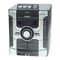
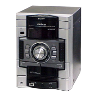
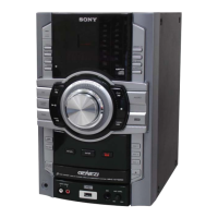
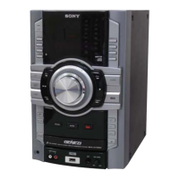
• HCD-GT111 is the amplifi er, USB, CD player, tape
deck and tuner section in MHC-GT111/GT111BP.
• HCD-GT222 is the amplifi er, USB, CD player, tape
deck and tuner section in MHC-GT222.
• HCD-GT444 is the amplifi er, USB, CD player, tape
deck and tuner section in MHC-GT444.
• HCD-GT555 is the amplifi er, USB, CD player, tape
deck and tuner section in MHC-GT555.
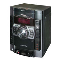
Photo: HCD-GT555
CD
Section
Model Name Using Similar Mechanism
NEW
Mechanism Type
CDM88A-K6BD93-WOD
Optical Pick-up Block Name
KSM-213DCP
Tape deck
Section
Model Name Using Similar Mechanism
HCD-EC55/EC77
Tape Transport Mechanism Type
TCM-J1 or CS-21SC-900TP
Amplifier section
HCD-GT555
The following are measured at AC 120, 127,
220, 230 – 240 V 50/60 Hz
Front speaker
Power output (rated): 110 W + 110 W
(at 6 Ω, 1 kHz, 1% THD)
RMS output power (reference):
200W + 200 W (per channel at 6 Ω,
1kHz,10%THD)
Subwoofer
RMS output power (reference): 190 W
(at 6 Ω,100Hz,10%THD)
HCD-GT444
The following are measured at AC 120, 127,
220, 230 – 240 V 50/60 Hz
Front speaker
Power output (rated): 90 W + 90 W
(at 6 Ω, 1 kHz, 1% THD)
RMS output power (reference):
150 W + 150 W (per channel at 6 Ω,
1 kHz, 10% THD)
Subwoofer
RMS output power (reference): 150 W
(at 6 Ω, 100 Hz, 10% THD)
HCD-GT222
The following are measured at AC 120, 127,
220, 230 – 240V 50/60 Hz
Power output (rated): 110 W + 110 W
(at 6 Ω, 1 kHz, 1% THD)
RMS output power (reference):
200 W + 200 W (per channel at 6 Ω,
1 kHz, 10% THD)
HCD-GT111
The following are measured at AC 120, 127,
220, 230 – 240V 50/60 Hz
Power output (rated): 60 W + 60 W
(at 6 Ω, 1 kHz, 1% THD)
RMS output power (reference):
100 W + 100 W (per channel at 6 Ω,
1 kHz, 10% THD)
Inputs
AUDIO INPUT L/R : voltage
250 mV, impedance 47 kilohms
MIC: sensitivity 1 mV, impedance
10 kilohms
(USB) port: Type A
Outputs
PHONES: accepts headphones of 8 Ω or
more
FRONT SPEAKER: accepts impedance of
6 Ω
SUBWOOFER (HCD-GT555/
HCD-GT444 only): accepts
impedance of 6 Ω
USB section
Supported bit rate
MP3 (MPEG 1 Audio Layer-3):
32 – 320 kbps, VBR
WMA: 32 – 192 kbps, VBR
AAC: 48 – 320 kbps
Sampling frequencies
MP3 (MPEG 1 Audio Layer-3):
32/44.1/48 kHz
WMA: 44.1 kHz
AAC: 44.1 kHz
Transfer speed
Full-Speed
Supported USB device
Mass Storage Class
Maximum current
500 mA
CD player section
System: Compact disc and digital audio
system
Laser Diode Properties
Emission Duration: Continuous
Laser Output*: Less than 44.6 μW
* This output is the value measurement
at a distance of 200 mm from the
objective lens surface on the Optical
Pick-up Block with 7 mm aperture.
Frequency response: 20 Hz – 20 kHz
Signal-to-noise ratio: More than 90 dB
Dynamic range: More than 88 dB
Tape deck section
Recording system: 4-track 2-channel, stereo
Tuner section
FM stereo, FM/AM superheterodyne tuner
FM tuner section
Tuning range:
87.5 – 108.0 MHz (50 kHz step)
Antenna: FM lead antenna
Antenna terminals: 75 ohms unbalanced
Intermediate frequency: 10.7 MHz
AM tuner section
Tuning range
Pan American and Oceanian models:
530 – 1,710 kHz (with 10 kHz tuning
interval)
531 – 1,710 kHz (with 9 kHz tuning
interval)
European and Russian models:
531 – 1,602 kHz (with 9 kHz tuning
interval)
Other models:
530 – 1,610 kHz (with 10 kHz tuning
interval)
531 – 1,602 kHz (with 9 kHz tuning
interval)
Antenna: AM loop antenna, external antenna
terminal
Intermediate frequency: 450 kHz
Mexican model: AC 127 V, 60 Hz
Argentine model: AC 220 V, 50/60 Hz
Other models: AC 120, 220 or 230 –
240 V, 50/60 Hz, Adjustable with
voltage selector
Power consumption
HCD-GT555: 216 W
HCD-GT444: 286 W
HCD-GT222: 163 W
HCD-GT111: 150 W
Dimensions (w/h/d) (excl. speakers)
Approx. 231 × 361 × 437.5 mm
(9 1/8 × 14 1/4 × 17 1/4 inch)
Mass (excl. speakers)
HCD-GT555/GT444/GT222
(Except European model),
HCD-ZT4: 10.0 kg (22 lb 1 oz)
HCD-GT222 (European model):
9.6 kg
HCD-GT111: 8.0 kg
Design and specifications are subject to
change without notice.
General
Power requirements
European and Russian models:
AC 230 V, 50/60 Hz