EasyManua.ls Logo

Sony HCD-GT22 Service Manual

Sony HCD-GT22
98 pages
To Next Page IconTo Next Page
Page #1 background imageLoading...
Page #1 background image
SERVICE MANUAL
COMPACT DISC DECK RECEIVER
SPECIFICATIONS
HCD-GT22/GT44/GT55
Photo: HCD-GT55
Ver. 1.0 2007.06
– Continued on next page –
9-887-722-01
2007F05-1
© 2007.06
Sony Corporation
Personal Audio Division
Published by Sony Techno Create Corporation
E Model
HCD-GT22/GT44/GT55
Australian Model
HCD-GT22/GT44
HCD-GT22 is the amplifier, USB, CD player, tape
deck and tuner section in MHC-GT22.
HCD-GT44 is the amplifier, USB, CD player, tape
deck and tuner section in MHC-GT44.
HCD-GT55 is the amplifier, USB, CD player, tape
deck and tuner section in MHC-GT55.
Model Name Using Similar Mechanism NEW
CD CD Mechanism Type CDM74KF-K6BD91UR-WOD
Section Base Unit Name BU-K6BD91UR-WOD74
Optical Pick-up Block Name KSM-213DCP
TAPE Model Name Using Similar Mechanism NEW
Section Tape Transport Mechanism Type CWN42FF609
Amplier section
HCD-GT55
The following are measured at AC 120, 127,
220, 240V 50/60Hz
Front speaker
Power output (rated): 110 W + 110 W
(at 6 , 1 kHz, 1% THD)
RMS output power (reference):
200 W + 200 W (per channel at 6 ,
1 kHz, 10% THD)
Subwoofer
RMS output power (reference): 190 W
(at 6 , 80 Hz, 10% THD)
HCD-GT44
The following are measured at AC 120, 127,
220, 240V 50/60Hz
Front speaker
Power output (rated): 90 W + 90 W
(at 6 , 1 kHz, 1% THD)
RMS output power (reference):
150 W + 150 W (per channel at 6 ,
1 kHz, 10% THD)
Subwoofer
RMS output power (reference): 150 W
(at 6 , 80 Hz, 10% THD)
HCD-GT22
The following are measured at AC 120, 127,
220, 240V 50/60Hz
Power output (rated): 110 W + 110 W
(at 6 , 1 kHz, 1% THD)
RMS output power (reference):
200 W + 200 W (per channel at 6 ,
1 kHz, 10% THD)
Inputs
AUDIO (phono jack): voltage 250 mV,
impedance 47 kilohms
MIC (phone jack): sensitivity 1 mV,
impedance 10 kilohms
(USB) port: Type A
Outputs
PHONES (stereo mini jack): accepts
headphones of 8 or more
SPEAKER: accepts impedance of 6 to 16
SUB WOOFER OUT (HCD-GT55/GT44
only): accepts impedance of 6 to 16
USB section
Supported bit rate
MP3 (MPEG 1 Audio Layer-3):
32 – 320 kbps, VBR
Sampling frequencies
MP3 (MPEG 1 Audio Layer-3):
32/44.1/48 kHz
Transfer speed
Full-Speed
Supported USB device
Mass Storage Class
Maximum current
500 mA
CD player section
System: Compact disc and digital audio
system
Laser: Semiconductor laser (λ=770 –
810 nm)
Emission duration: continuous
Frequency response: 20 Hz – 20 kHz
Signal-to-noise ratio: More than 90 dB
Dynamic range: More than 88 dB
w
w
w
.
x
i
a
o
y
u
1
6
3
.
c
o
m
Q
Q
3
7
6
3
1
5
1
5
0
9
9
2
8
9
4
2
9
8
T
E
L
1
3
9
4
2
2
9
6
5
1
3
9
9
2
8
9
4
2
9
8
0
5
1
5
1
3
6
7
3
Q
Q
TEL 13942296513 QQ 376315150 892498299
http://www.xiaoyu163.com

Table of Contents

Other manuals for Sony HCD-GT22

Question and Answer IconNeed help?

Do you have a question about the Sony HCD-GT22 and is the answer not in the manual?

Sony HCD-GT22 Specifications

General IconGeneral
BrandSony
ModelHCD-GT22
CategoryStereo System
LanguageEnglish

Summary

Specifications Overview

Amplifier Section Details

Power output and RMS output for HCD-GT55/GT44/GT22 amplifier sections.

Inputs, Outputs, USB, and CD Player Specs

Details on audio/mic inputs, speaker/headphone outputs, and USB/CD player performance.

Technical Specifications Overview

Tape Deck and Tuner Specifications

Recording system, frequency response, and tuner details for tape and radio functions.

General System Information and Precautions

Power requirements, dimensions, mass, handling notes, and safety cautions.

Servicing Notes and Procedures

Servicing Notes - Handling and Safety

Precautions for optical pick-up, laser diode, solder, and antitheft lock.

Disassembly Instructions

Flowchart, case removal, and board disassembly steps.

Test Modes and Adjustments

Procedures for test modes, mechanical, and electrical adjustments.

Diagrams and Parts Lists

Block diagrams, PWB layouts, schematics, exploded views, and parts list.

Service Position and Tray Operation

Service Position Setup for CD Mechanism

Preparing jigs for checking the CD mechanism deck.

Opening the CD Tray with Power Off

Procedure to manually open the CD tray when the unit is powered off.

General Controls Overview

Unit and Remote Control Functions

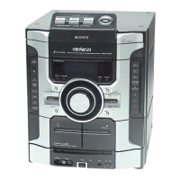
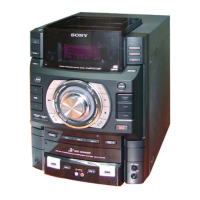
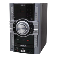
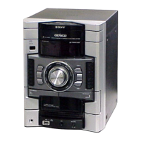
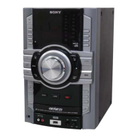
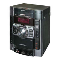
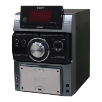
Description of controls on the HCD-GT55 unit and its remote.

Disassembly Procedures

Disassembly Flowchart

Step-by-step guide for disassembling the unit.

Disassembly - Case and Lid Removal

Removing Side and Top Cases

Instructions for detaching the left, right side, and top cases.

Disassembly - CD Mechanism and USB Board

Removing CD Lid and Mechanism Components

Steps for detaching the CD lid, mechanism deck, and USB board.

Disassembly - Front Panel and Mecha Deck

Removing Front Panel and Mecha Deck

Steps for disassembling the front panel and Mecha Deck (CWN42FF609).

Disassembly - Rear and Main Boards

Removing Back Panel and Main Board

Instructions for disassembling the back panel and Main Board.

Disassembly - CD and Driver Boards

Removing CD, Driver, and SW Boards

Steps for disassembling the CD, Driver, and SW boards.

Disassembly - Optical Pick-up and Sensor Boards

Removing Optical Pick-up and Sensor Boards

Procedures for disassembling the optical pick-up block and sensor board.

Disassembly - Motor Boards

Disassembling Motor (TB) and (LD) Boards

Steps for removing the Motor TB and Motor LD boards.

Test Modes - Core Functions

Cold Reset and Tuning Step Change

Procedures for resetting the unit and adjusting AM tuning steps.

CD Ship Lock and Antitheft Lock Modes

Modes for shipping preparation and preventing unauthorized disc removal.

Amplifier and MC Test Modes

Modes for testing amplifier IC parameters and microprocessor functions.

Test Mode - Version and Error Information

Version Display Mode

Checking model, destination, and software versions.

CD Error Code Display Mode

Retrieving and displaying CD mechanism and optical pick-up error codes.

Test Mode - Advanced Functions

Repeat Limit Cancel and CD/USB Power Management

Enabling unlimited CD repeats and managing CD/USB power modes.

Booster, Exciter, and CD Service Modes

Controls for audio enhancement features and CD sled motor operation.

Panel Test Mode

Panel Test Mode Operations

Checking display segments, LEDs, keys, and control knobs.

Mechanical Adjustments

Precautions and Torque Measurement

Safety guidelines for adjustments and torque specifications.

Tape Tension Measurement

Procedure for measuring tape tension.

Electrical Adjustments

Deck Section and Azimuth Adjustment

Adjustments for the deck section and record/playback head azimuth.

Tuner and CD Section Checks

FM Tune Level Check

Verifying FM reception performance and tuning indication.

CD Focus Bias Check

Assessing optical pick-up focus bias by observing the eye pattern.

Diagrams - Block Diagrams

Block Diagram - CD Servo, USB Section

Functional overview of the CD servo and USB data paths.

Diagrams - Block Diagrams

Block Diagram - Main Section

Illustrates the signal flow within the main processing unit.

Diagrams - Block Diagrams

Block Diagram - Amplifier Section

Details the audio signal paths and amplification stages.

Diagrams - Block Diagrams

Block Diagram - Panel and Power Amp Section

Shows connections to panel controls and power amplifier.

Diagrams - Board Layouts and Schematics

Printed Wiring Boards Overview

Component layouts for various circuit boards.

Schematic Diagrams Overview

Circuit schematics for different system sections and boards.

Exploded Views and Parts Location

Visual component breakdowns and circuit board identification.

Printed Wiring Board - CD Board

CD Board Component and Conductor Layouts

Visual representation of CD board components and traces.

Schematic Diagram - CD Board

CD Board Circuit Details

Detailed schematic of the CD section circuitry, including ICs and connections.

Printed Wiring Boards - Change Section

Change Section Board Layouts

Component layouts for motor, sensor, driver, and SW boards.

Schematic Diagram - Change Section

Change Section Circuit Schematics

Circuit details for motor drives and control logic.

Printed Wiring Board - USB Board

USB Board Component and Conductor Layouts

Visual layout of the USB board's components and traces.

Schematic Diagram - USB Board

USB Board Circuit Details

Detailed circuit schematic for the USB controller and related components.

Printed Wiring Board - TC Board

TC Board Component Layout

Component placement diagram for the TC board.

Schematic Diagram - TC Board

TC Board Circuit Schematic

Detailed circuit diagram for the TC board, including ICs and transistors.

Waveform Examples

CD Board Waveforms

Illustrates eye patterns for RFI and XO signals during CD playback.

USB and Panel Board Waveforms

Shows waveforms for USB controller and panel driver ICs.

Printed Wiring Boards - Main Section

Main Board Component Layout

Detailed component placement for the Main Board.

Schematic Diagram - Main Section (1/4)

Main Board Circuit Schematic Part 1

Circuit details for system controller and interface signals.

Schematic Diagram - Main Section (2/4)

Main Board Circuit Schematic Part 2

Circuit paths for tuner, tape, CD, and audio functions.

Schematic Diagram - Main Section (3/4)

Main Board Circuit Schematic Part 3

Circuit details for bus switches, USB controller, and power supply.

Schematic Diagram - Main Section (4/4)

Main Board Circuit Schematic Part 4

Circuit details for power amplifier, protection, and fan control.

Printed Wiring Board - MIC Board

MIC Board Component Layout

Component placement diagram for the MIC board.

Schematic Diagram - MIC Board

MIC Board Circuit Schematic

Detailed circuit for microphone input and USB interface.

Printed Wiring Board - AMP Board (GT22/GT55)

AMP Board (GT22/GT55) Layout

Component placement for the GT22/GT55 amplifier board.

Schematic Diagram - AMP Board (GT22/GT55)

AMP Board (GT22/GT55) Circuit Details

Detailed circuit for the amplifier section.

Printed Wiring Board - AMP Board (GT44)

AMP Board (GT44) Layout

Component placement for the GT44 amplifier board.

Schematic Diagram - AMP Board (GT44)

AMP Board (GT44) Circuit Details

Detailed circuit for the GT44 amplifier section.

Printed Wiring Boards - SUB WOOFER Section (GT44/GT55)

SUB WOOFER Board Layout

Component placement for the SUB WOOFER board.

Schematic Diagram - SUB WOOFER Section (GT44/GT55)

SUB WOOFER Board Circuit Schematic

Detailed circuit for the SUB WOOFER amplifier.

Printed Wiring Boards - PANEL Section

PANEL Board Component Layouts

Component placement for the front panel and volume boards.

Schematic Diagram - PANEL Section

PANEL Board Circuit Schematic

Circuit details for the panel controls and display driver IC.

Printed Wiring Boards - KEY Section

KEY Board Layouts

Component placement for the KEY Left, TOP, and RIGHT boards.

Schematic Diagram - KEY Section

KEY Section Circuit Schematics

Detailed circuit diagrams for the key switches and controls.

Printed Wiring Board - TRANS Board (GT22/GT55)

TRANS Board (GT22/GT55) Layout

Component placement for the GT22/GT55 transformer board.

Schematic Diagram - TRANS Board (GT22/GT55)

TRANS Board (GT22/GT55) Circuit Schematic

Circuit diagram for the power transformer and voltage selector.

Printed Wiring Board - TRANS Board (GT44)

TRANS Board (GT44) Layout

Component placement for the GT44 transformer board.

Schematic Diagram - TRANS Board (GT44)

TRANS Board (GT44) Circuit Schematic

Circuit diagram for the GT44 power transformer and voltage selector.

IC Block Diagrams

CD, Main, Driver, USB IC Block Diagrams

Functional block diagrams for key ICs across CD, Main, Driver, and USB boards.

IC Block Diagrams

Panel Board IC Block Diagram

Functional block diagram for the Panel Board IC (IC701).

IC Pin Function Descriptions

CD Board IC101 Pin Functions

Detailed pin assignments for the CD-MP3 Processor IC.

IC Pin Function Descriptions

CD Board IC101 Pin Functions

Detailed pin assignments for the CD-MP3 Processor IC.

IC Pin Function Descriptions

USB Board IC901 Pin Functions

Detailed pin assignments for the USB Controller IC.

IC Pin Function Descriptions

Main Board IC901 Pin Functions

Detailed pin assignments for the System Controller IC.

Exploded Views - Case Section

Case Section Component Breakdown

Visual parts list for the unit's exterior casing and panels.

Exploded Views - Key Top Board

Key Top Board Component Details

Part numbers and descriptions for key top board components.

Exploded Views - TC Mecha Deck

TC Mecha Deck Component Details

Part numbers and descriptions for TC Mecha Deck components.

Exploded Views - Panel Board

Panel Board Component Details

Part numbers and descriptions for panel board components.

Exploded Views - Front Panel Section

Front Panel Component Details

Part numbers and descriptions for front panel components.

Exploded Views - Main Board Section

Main Board Component Details

Part numbers and descriptions for Main Board components.

Exploded Views - Power and Subwoofer Boards

Power and Subwoofer Board Component Details

Part numbers for screws and belts related to power and subwoofer boards.

Exploded Views - Chassis Section

Chassis Component Details

Part numbers for chassis, fuses, transformers, and power cords.

Exploded Views - CD Mechanism Deck Section 1

CD Mechanism Deck Section 1 Component Details

Part numbers for CD mechanism deck parts and motor.

Exploded Views - CD Mechanism Deck Section 2

CD Mechanism Deck Section 2 Component Details

Part numbers for driver board, switches, and optical pick-up block.

Electrical Parts List - 5V REG and AMP Board Components

5V REG Board Components

List of capacitors, diodes, ICs, resistors for 5V REG board.

AMP Board Components

List of capacitors, resistors, transistors, and relays for AMP board.

Electrical Parts List - AMP Board Resistors

AMP Board Resistors

Detailed list of resistors for the AMP board.

Electrical Parts List - AMP and CD Board Components

AMP Board Capacitors and Fuses

List of capacitors and fuses for the AMP board.

CD Board Capacitors, Connectors, Diodes

Parts list for CD board capacitors, connectors, and diodes.

Electrical Parts List - D-Light Sync, Driver, Key Boards

D-Light Sync, Driver, Key Board Components

Parts list for D-Light Sync, Driver, Key Left, and Key Right boards.

Electrical Parts List - Key Top Board and Resistors

Key Top Board Components and Resistors

Resistors and switches for the Key Top board.

Key Right Board Components

Resistors and switches for the Key Right board.

Electrical Parts List - Key Top and Main Boards

Key Top Board Resistors and Switches

Resistors and switches for the Key Top board.

Main Board Components (GT44/GT55)

Parts list for Main Board versions GT44/GT55.

Electrical Parts List - Main Board Capacitors

Main Board Capacitors (GT44/GT55)

List of capacitors for Main Board versions GT44/GT55.

Electrical Parts List - Main Board Connectors, ICs, Transistors

Main Board Connectors, ICs, Transistors

Parts list for Main Board connectors, ICs, and transistors.

Electrical Parts List - Main Board Resistors

Main Board Resistors (GT44/GT55)

Detailed list of resistors for Main Board versions GT44/GT55.

Electrical Parts List - Main Board Resistors

Main Board Resistors (GT44/GT55)

Continued list of resistors for Main Board versions GT44/GT55.

Electrical Parts List - Main and MIC Board Resistors

Main and MIC Board Resistors

List of resistors for Main Board (GT44/GT55) and MIC Board.

Electrical Parts List - MIC, Motor, Panel Components

MIC, Motor, Panel Board Components

Parts for MIC, Motor LD/TB boards, and Panel board connectors.

Electrical Parts List - Panel Board Components

Panel Board Components

Detailed list of resistors, transistors, LEDs, and capacitors for the Panel Board.

Electrical Parts List - SW, SW-SP, TC Boards

SW, SW-SP, TC Board Components

Parts for SW, SW-SP, and TC boards, including switches and capacitors.

Electrical Parts List - Trans and USB Board Components

Trans Board Components

Fuses, connectors, diodes, ICs, and jumper resistors for the Trans Board.

USB Board Components

Capacitors, connectors, diodes, ICs, resistors, and switches for the USB Board.

Electrical Parts List - TC and Trans Board Resistors

TC Board Resistors

List of resistors for the TC board.

Trans Board Resistors, Connectors, Diodes

Resistors, connectors, and diodes for the Trans Board.

Electrical Parts List - Trans and USB Board Components

Trans Board Components

Fuses, transformers, connectors, diodes, ICs, resistors for Trans Board.

USB Board Components

Capacitors, connectors, diodes, ICs, resistors, and switches for USB Board.

Electrical Parts List - USB, Volume, Miscellaneous Components

USB and Volume Board Components

Resistors, network resistors, and capacitors for USB and Volume boards.

Miscellaneous and Accessories

Adapters, fuses, and other miscellaneous parts.

Memo

Revision History

Related product manuals