Do you have a question about the Sony HCD-GT444 and is the answer not in the manual?
Details on power output and impedance for front speakers and subwoofer.
Specifications related to the CD player mechanism.
Specifications for the tape deck mechanism.
Specifications for FM/AM tuner, including tuning range and frequency.
Details on supported bit rates and sampling frequencies for USB playback.
System details for the compact disc and digital audio system.
Guidelines for safely handling the optical pick-up block and its flexible board.
Procedure for checking laser diode emission, emphasizing safe observation distance.
Information on characteristics and handling of unleaded solder for repairs.
Procedure to unlock the disc tray, often used for antitheft demonstration.
Procedure to discharge capacitors on the MAIN board for electric shock prevention.
Details on placing the CD mechanism block in a specific position for service.
Illustrates the service position of the poweramp board.
Guide to distinguish between the two types of tape mechanism decks installed.
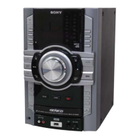
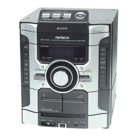
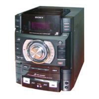
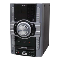
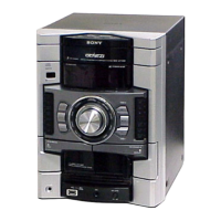
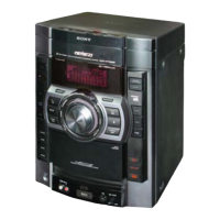
Explains the front and top view parts and their functions.
Details the functions of each button on the RM-AMU006 remote control.
Step-by-step guide for connecting speakers, antennas, power, and subwoofer.
Procedure for setting the system clock, including display and power loss notes.
Provides a step-by-step flow chart for disassembling the unit.
Procedures for removing the side cases and the top panel block.
Procedures for removing the tape mechanism deck and front panel block.
Procedures for removing the back panel and the main board.
Procedures for removing the CD mechanism block and poweramp board.
Procedures for removing the base unit and optical pick-up base assembly.
Procedure for replacing the belt (DLM3A) and its associated parts.
Checks fluorescent indicators, LEDs, keys, volume jog, and software version.
Tests for GEQ MAX/MIN/FLAT and MASTER VOLUME responses.
Checks tape function behavior when starting recording.
Clears all preset data, including EEPROM, to initial conditions.
Switches the Variable Attenuation Control System (VACS) ON or OFF.
Checks operations of Amplifier and Tape sections.
Covers tuner step change, CD service, CD aging, and error code modes.
Details error displays and procedures for CD ship modes with/without memory clear.
Procedures for CD tray lock, factory preset, VACS display, and meter touch count.
Precautions for cleaning parts, demagnetizing heads, and using tools for adjustments.
Guidelines for measuring torque for FWD, Back Tension, FF, and REV modes.
Procedure for measuring tape tension in FWD mode.
Covers deck section adjustments, test tape procedures, and azimuth alignment.
Procedures for checking FM tuning level and RF signal level.
Block diagram illustrating the CD servo and USB interface sections.
Block diagram showing the main section of the system, including tuner and audio inputs.
Block diagram illustrating the amplifier section, including power amp and protection circuits.
Block diagram of the panel and power supply sections, including regulators and LEDs.
Schematic diagram for the CD board, part 1 of 2.
Schematic diagram for the CD board, part 2 of 2.
Layout of the CD board's component and conductor sides.
Layout of the USB board's component and conductor sides.
Schematic diagram for the USB board, illustrating its circuitry and connections.
Layout of the MAIN board's component and conductor sides.
Schematic diagram for the MAIN board, part 1 of 4.
Schematic diagram for the MAIN board, part 2 of 4.
Schematic diagram for the MAIN board, part 3 of 4.
Schematic diagram for the MAIN board, part 4 of 4.
Layout of the TRANS1 board for specific GT111 models.
Schematic for the TRANS1 board for specific GT111 models.
Layout of the TRANS2 board for GT222/GT444/GT555 models.
Schematic for the TRANS2 board for GT222/GT444/GT555 models.
Layout of the TRANSX board for GT111 AEP, Russian, Argentina models.
Schematic for the TRANSX board for GT111 AEP, Russian, Argentina models.
Common notes for diagrams and a guide to circuit board locations.
Layout of the TC board's component and conductor sides.
Schematic diagram for the TC board, showing its components and connections.
Layouts for the 5V REG and 9V REG boards.
Schematics for the 5V REG and 9V REG circuits.
Layouts for the MIC board and SW JACK board.
Schematics for the MIC board and SW JACK board, including audio inputs.
Illustrates typical waveforms for CD, USB, and TC boards.
Block diagrams for key ICs like IC401, IC501, IC502, IC901.
Pin functions and block diagram for IC407 R2A15216FP.
Pin functions and block diagrams for IC670, 672 TC74HC4066AFT.
Pin functions and block diagram for IC673 TC74VHC157FT.
Description of IC1101 NJU3427FH2 for the display board.
Description of IC001 LB1846M for the motor drive board.
Detailed pin function descriptions for the CD-MP3 Processor IC101.
Continued detailed pin function descriptions for the CD-MP3 Processor IC101.
Detailed pin function descriptions for the USB Controller IC901.
Continued pin function descriptions for the USB Controller IC901.
Detailed pin function descriptions for the System Controller IC401.
Continued pin function descriptions for the System Controller IC401.
Exploded view of the unit's case, showing panels and screws.
Exploded view of the loading panel section and its components.
Exploded view of the display board assembly and its controls.
Exploded view of the front panel section, showing controls and indicators.
Exploded view of the meter display assembly and its components.
Exploded view of the top panel section, including tape deck and TC board.
Exploded view of the back panel section, showing ports and connectors.
Exploded view of the main board and its associated components.
Exploded view of the unit's chassis, showing power transformers and fuses.
Exploded view of the CD mechanism assembly and its parts.
List of capacitors and diodes for the 5V regulator board.
List of capacitors and ICs for the 9V regulator board.
List of capacitors, connectors, diodes, resistors, transistors, and ICs for the CD board.
List of resistors, connectors, ICs, transistors, and relays for the MAIN board.
Parts lists for DISPLAY, LED, and LED (GSL1) boards.
List of resistors and switches for the DISPLAY board.
List of capacitors and resistors for DISPLAY and LED boards.
List of capacitors for the MAIN board.
Lists connectors, diodes, ICs, transistors, and relays for the MAIN board.
List of transistors and resistors for the MAIN board.
List of resistors for the MAIN board.
List of resistors for the MAIN board.
List of capacitors, ICs, and jumpers for the MIC board.
List of jacks, resistors, and variable resistors for the MIC board.
Parts list for the motor drive board.
List of capacitors, connectors, diodes, fuses, transformers, resistors, and relays for the poweramp board.
List of resistors, transistors, and relays for the poweramp board.
List of resistors, fuses, switches, and transistors for the SW board.
List of resistors, coils, and fuses for the SW JACK board.
List of capacitors, connectors, diodes, jumpers, transistors, and resistors for the TC board.
Lists capacitors, connectors, diodes, jumpers, transistors, and resistors for the TC board.
Parts list for the TRANS1 board, including various components.
List of switches and resistors for the TRANS1 board.
Parts list for the TRANS2 board, including various components.
List of switches and resistors for the TRANS2 board.
Parts list for the TRANSX board, including various components.
Parts list for the TRANSX board, including various components.
Parts list for the USB board, including capacitors, connectors, diodes, jumpers, resistors.
List of resistors, switches, and volume components for the USB board.
List of miscellaneous parts like filters, cables, and boards.
List of accessory parts such as the power adaptor.
Details the version and date of revisions to the service manual.
| Brand | Sony |
|---|---|
| Model | HCD-GT444 |
| Category | Stereo System |
| Language | English |