EasyManua.ls Logo

Sony HCD-GT44 Service Manual

Sony HCD-GT44
98 pages
To Next Page IconTo Next Page
Page #1 background imageLoading...
Page #1 background image
SERVICE MANUAL
COMPACT DISC DECK RECEIVER
SPECIFICATIONS
HCD-GT22/GT44/GT55
Photo: HCD-GT55
Ver. 1.0 2007.06
– Continued on next page –
9-887-722-01
2007F05-1
© 2007.06
Sony Corporation
Personal Audio Division
Published by Sony Techno Create Corporation
E Model
HCD-GT22/GT44/GT55
Australian Model
HCD-GT22/GT44
HCD-GT22 is the amplifier, USB, CD player, tape
deck and tuner section in MHC-GT22.
HCD-GT44 is the amplifier, USB, CD player, tape
deck and tuner section in MHC-GT44.
HCD-GT55 is the amplifier, USB, CD player, tape
deck and tuner section in MHC-GT55.
Model Name Using Similar Mechanism NEW
CD CD Mechanism Type CDM74KF-K6BD91UR-WOD
Section Base Unit Name BU-K6BD91UR-WOD74
Optical Pick-up Block Name KSM-213DCP
TAPE Model Name Using Similar Mechanism NEW
Section Tape Transport Mechanism Type CWN42FF609
Amplier section
HCD-GT55
The following are measured at AC 120, 127,
220, 240V 50/60Hz
Front speaker
Power output (rated): 110 W + 110 W
(at 6 , 1 kHz, 1% THD)
RMS output power (reference):
200 W + 200 W (per channel at 6 ,
1 kHz, 10% THD)
Subwoofer
RMS output power (reference): 190 W
(at 6 , 80 Hz, 10% THD)
HCD-GT44
The following are measured at AC 120, 127,
220, 240V 50/60Hz
Front speaker
Power output (rated): 90 W + 90 W
(at 6 , 1 kHz, 1% THD)
RMS output power (reference):
150 W + 150 W (per channel at 6 ,
1 kHz, 10% THD)
Subwoofer
RMS output power (reference): 150 W
(at 6 , 80 Hz, 10% THD)
HCD-GT22
The following are measured at AC 120, 127,
220, 240V 50/60Hz
Power output (rated): 110 W + 110 W
(at 6 , 1 kHz, 1% THD)
RMS output power (reference):
200 W + 200 W (per channel at 6 ,
1 kHz, 10% THD)
Inputs
AUDIO (phono jack): voltage 250 mV,
impedance 47 kilohms
MIC (phone jack): sensitivity 1 mV,
impedance 10 kilohms
(USB) port: Type A
Outputs
PHONES (stereo mini jack): accepts
headphones of 8 or more
SPEAKER: accepts impedance of 6 to 16
SUB WOOFER OUT (HCD-GT55/GT44
only): accepts impedance of 6 to 16
USB section
Supported bit rate
MP3 (MPEG 1 Audio Layer-3):
32 – 320 kbps, VBR
Sampling frequencies
MP3 (MPEG 1 Audio Layer-3):
32/44.1/48 kHz
Transfer speed
Full-Speed
Supported USB device
Mass Storage Class
Maximum current
500 mA
CD player section
System: Compact disc and digital audio
system
Laser: Semiconductor laser (λ=770 –
810 nm)
Emission duration: continuous
Frequency response: 20 Hz – 20 kHz
Signal-to-noise ratio: More than 90 dB
Dynamic range: More than 88 dB
w
w
w
.
x
i
a
o
y
u
1
6
3
.
c
o
m
Q
Q
3
7
6
3
1
5
1
5
0
9
9
2
8
9
4
2
9
8
T
E
L
1
3
9
4
2
2
9
6
5
1
3
9
9
2
8
9
4
2
9
8
0
5
1
5
1
3
6
7
3
Q
Q
TEL 13942296513 QQ 376315150 892498299
http://www.xiaoyu163.com

Table of Contents

Other manuals for Sony HCD-GT44

Question and Answer IconNeed help?

Do you have a question about the Sony HCD-GT44 and is the answer not in the manual?

Sony HCD-GT44 Specifications

General IconGeneral
Speakers IncludedYes
CD PlayerYes
Number of Discs1
Cassette DeckYes
Radio TunerYes
BluetoothNo
Remote ControlYes
TypeMini System
Speaker Configuration2.0
Speaker TypeBass Reflex
Tuner BandsAM/FM
Preset Stations30
Audio InputYes

Summary

SPECIFICATIONS

System Specifications Overview

Details amplifier, input/output, USB, CD player, tape deck, tuner, and general specs.

SERVICING NOTES

Handling Precautions and Special Modes

Precautions for optical pick-up, laser diode, soldering, and antithet lock.

Service Position and Tray Opening

Procedures for setting up for servicing and opening the tray with power off.

GENERAL

Location of Controls

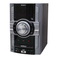
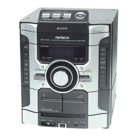
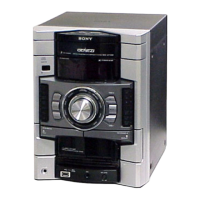
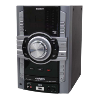
Identifies the location and function of controls on the unit and remote.

DISASSEMBLY

Disassembly Flow and Case Removal

Provides the overall disassembly sequence and steps for removing outer cases.

Internal Component and Board Removal

Procedures for removing internal mechanisms, panels, and circuit boards.

TEST MODE

Reset, Tuning, and Lock Modes

Covers cold reset, tuning step, CD ship lock, and antithet lock modes.

Diagnostic and Special Function Modes

Includes version display, error codes, and special function modes for testing.

DIAGRAMS

Block Diagrams

Illustrates functional blocks for CD Servo, USB, Main, Amplifier, Panel, and TRANS sections.

Printed Wiring Boards (PWBs) and Schematics

Layouts and detailed schematics for CD, USB, TC, MAIN, AMP, SUB WOOFER, PANEL, and KEY sections.

IC and Transistor Information

Provides block diagrams, pin functions, and descriptions for key ICs and transistors.

EXPLODED VIEWS AND PARTS LIST

Exploded Views of Assemblies

Illustrates exploded views of major assemblies like cases, panels, and mechanisms.

Electrical Component List

Comprehensive list of electrical components with part numbers and descriptions.

Related product manuals