EasyManua.ls Logo

Sony HCD-GTR7 User Manual

Sony HCD-GTR7
92 pages
To Next Page IconTo Next Page
Page #1 background imageLoading...
Page #1 background image
1
HCD-GTR6/GTR6B/GTR7/GTR8/GTR8B
Ver. 1.0 2009. 05
SERVICE MANUAL
E Model
HCD-GTR6/GTR6B/GTR7/GTR8/GTR8B
Australian Model
HCD-GTR6B/GTR8B
AUDIO POWER SPECIFICATION
Amplifi er section
MHC-GTR8 (HCD-GTR8/HCD-GTR8B)
The following are measured at
Mexican model: AC 127 V, 60 Hz
Other models: AC 120, 220, 240 V, 50/60 Hz
Front/Surround speaker
Power Output (rated): 210 W + 210 W (at 6 Ω, 1 kHz, 1% THD,
at LINK MODE)
Front speaker
RMS output power (reference):
280 W + 280 W (per channel at 8 Ω,
1 kHz, 10% THD)
Surround speaker
RMS output power (reference):
110 W + 110 W (per channel at 24 Ω,
1 kHz, 10% THD)
Subwoofer
RMS output power (reference):
160 W + 160 W (per channel at 6 Ω,
100 Hz, 10% THD)
SPECIFICATIONS
MHC-GTR7 (HCD-GTR7)
The following are measured at
Mexican model: AC 127 V, 60 Hz
Other models: AC 120, 220, 240 V, 50/60 Hz
Front/Surround speaker
Power Output (rated): 215 W + 215 W (at 6 Ω, 1 kHz, 1% THD, at LINK MODE)
Front speaker
RMS output power (reference):
285 W + 285 W (per channel at 8 Ω, 1 kHz, 10% THD)
Surround speaker
RMS output power (reference): 110 W + 110 W (per channel at 24 Ω,
1 kHz, 10% THD)
Subwoofer
RMS output power (reference): 210 W (at 8 Ω, 100 Hz, 10% THD)
Sony Corporation
Audio & Video Business Group
Published by Sony EMCS (Malaysia) PG Tec
9-890-515-01
2009E08-1
© 2009. 05
– Continued on next page –
COMPACT DISC DECK RECEIVER
• HCD-GTR6/GTR7/GTR8
are the tuner, CD and
amplifi er section in
MHC-GTR6/GTR7/GTR8
• HCD-GTR6B/GTR8B
are the tuner, deck, CD and
amplifi er section in
MHC-GTR6/GTR7/GTR8
Photo : HCD-GTR8B (E Model)
HCD-GTR6/GTR6B/GTR7/GTR8/GTR8B
CD
Section
Model Name Using Similar Mechanism NEW
CD Mechanism Type CDM74HF-DVBU101//M
Optical Pick-up Name KHM-313CAB/C2NP
Tape Deck Section
only for HCD-GTR6B/GTR8B
Model Name Using Similar Mechanism HCD-GTX777/GTX787/GTX888
Tape Mechanism Type CFP42608

Table of Contents

Question and Answer IconNeed help?

Do you have a question about the Sony HCD-GTR7 and is the answer not in the manual?

Sony HCD-GTR7 Specifications

General IconGeneral
Speaker Configuration2.0
CD PlayerYes
Radio TunerYes
BluetoothNo
USB PortYes
USB PlaybackYes
Remote ControlYes
TypeMini Hi-Fi System
FunctionsCD, USB, Radio
Tuner BandsFM, AM

Summary

SERVICE MANUAL

E Model

Model designation for E models.

Australian Model

Model designation for Australian models.

SPECIFICATIONS

AUDIO POWER SPECIFICATION

Detailed audio power output specifications for different models.

General and Component Specifications

USB, Disc Player, Tape Deck, and Tuner specifications.

SAFETY AND HANDLING NOTES

Component Handling and Solder Precautions

Precautions for chip components, solder, and flexible circuits.

Laser Diode and Optical Pick-up Safety

Safety measures for laser diode emission and optical pick-up handling.

MODEL IDENTIFICATION

Model Number Label Location

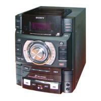
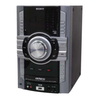
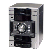
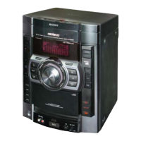
Location and details of the model number label.

SECTION 1 DISASSEMBLY

Component Disassembly Procedures

Step-by-step procedures for disassembling unit components and boards.

SECTION 2 TEST MODE

Operational and System Test Modes

GC TEST, MC TEST, COLD RESET, VACS, TUNER STEP CHANGE modes.

Ship, Lock, and Meter Test Modes

CD SHIP, TRAY LOCK, TCM OFFLINE, VACS DISPLAY, METER AGING, ERROR CODE modes.

SECTION 3 MECHANICAL ADJUSTMENTS

Adjustment Precautions and Torque Measurement

Precautions and torque measurement for mechanical adjustments.

SECTION 4 ELECTRICAL ADJUSTMENTS

Tuner and Deck Electrical Adjustments

FM tune level check and head azimuth adjustment procedures.

SECTION 5 DIAGRAMS

System Block Diagrams

Block diagrams for system sections like USB, RF/Servo, Main, Amp.

Circuit Board Locations

Location of various circuit boards within the unit.

Printed Wiring Diagrams

Printed wiring diagrams for various boards.

Schematic Diagrams

Schematic diagrams for various boards.

IC Block Diagrams

Block diagrams for specific integrated circuits.

MAIN BOARD IC500 (SYSTEM CONTROL)

IC500 Pin Assignments and Descriptions

Detailed pin assignments and descriptions for the IC500 system control IC.

SECTION 6 EXPLODED VIEWS

Exploded Views of Major Sections

Exploded views for Main, Back Panel, Front Panel, Chassis, and CD Mechanism sections.

SECTION 7 ELECTRICAL PARTS LIST

Component Lists by Board

Electrical components listed by board (CD SW, Display, DMB19, Main, MIC, etc.).

Miscellaneous Parts List

List of miscellaneous parts including wires, fuses, motors, fans, tuners.

REVISION HISTORY

Document Revision Log

Records of document revisions and updates.

Related product manuals