EasyManua.ls Logo

Sony HCD-GZR9D User Manual

Sony HCD-GZR9D
128 pages
To Next Page IconTo Next Page
Page #1 background imageLoading...
Page #1 background image
SERVICE MANUAL
Sony Corporation
Audio&Video Business Group
Published by Sony Techno Create Corporation
HCD-GZR7D/GZR8D/
GZR9D
DVD DECK RECEIVER
9-889-156-02
2008G04-1
©
2008.07
E Model
HCD-GZR7D/GZR8D/GZR9D
Australian Model
HCD-GZR9D
Russian Model
HCD-GZR7D/GZR9D
Ver. 1.1 2008.07
HCD-GZR7D/GZR8D/GZR9D are the
tuner, deck, DVD and ampli er section
in MHC-GZR7D/GZR8D/GZR9D.
Photo: HCD-GZR8D
DVD
Section
Model Name Using Similar Mechanism HCD-GNZ777D/GNZ888D
DVD Mechanism Type CDM74HF-DVBU101//C
Optical Pick-up Name KHM-313CAB/C2RP
Tape Deck
Section
Model Name Using Similar Machanism HCD-GNZ777D/GNZ888D
SPECIFICATIONS
Ampli er Section
The following measured at AC 230 V, 50/60 Hz (Russian model)
The following measured at AC 127, 220, 240 V, 50/60 Hz
(Saudi Arabian model)
The following measured at AC 120, 220, 240 V, 50/60 Hz (Other models)
MHC-GZR9D
Power output (rated): 100 W + 100 W (6 Ω at 1 kHz, 1% THD)
RMS output power (reference)
Front speaker: 180 W + 180 W (per channel at 6 Ω, 1 kHz,
10% THD)
Center speaker: 60 W (6 Ω at 1 kHz, 10% THD)
Surround speaker: 60 W + 60 W (per channel at 6 Ω, 1 kHz,
10% THD)
Subwoofer: 180 W (6 Ω at 80 Hz, 10% THD)
MHC-GZR8D
Power output (rated): 100 W + 100 W (6 Ω at 1 kHz, 1% THD)
RMS output power (reference)
Front speaker: 180 W + 180 W (per channel at 6 Ω, 1 kHz,
10% THD)
Center speaker: 60 W (6 Ω at 1 kHz, 10% THD)
Surround speaker: 60 W + 60 W (per channel at 6 Ω, 1 kHz,
10% THD)
MHC-GZR7D
Power output (rated): 100 W + 100 W (6 Ω at 1 kHz, 1% THD)
RMS output power (reference):
180 W+ 180 W (per channel at 6 Ω, 1 kHz,
10% THD)
Inputs
VIDEO/SAT VIDEO IN (phono jack):
1 Vp-p, 75 ohms
VIDEO/SAT AUDIO IN L/R (phono jacks):
voltage 250/450 mV, impedance 47 kilohms
MIC 1/MIC 2 (phone jacks):
sensitivity 1 mV, impedance 10 kilohms
– Continued on next page –

Table of Contents

Question and Answer IconNeed help?

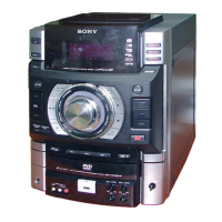
Do you have a question about the Sony HCD-GZR9D and is the answer not in the manual?

Sony HCD-GZR9D Specifications

General IconGeneral
TypeMini Hi-Fi System
Number of Discs1
Speakers IncludedYes
Speaker Impedance6 Ohms
FunctionsCD Receiver with AM/FM Tuner
Tuner BandsAM/FM
Total Power Output330W
Supported DiscsCD, CD-R, CD-RW
Preset Stations20 FM, 10 AM

Summary

HCD-GZR7D/GZR8D/GZR9D Model Identification

Specifications Overview

Provides technical specifications for amplifier, inputs, and general features.

HCD-GZR7D/GZR8D/GZR9D Specifications

Output and Disc Player Specifications

Lists specifications for output terminals and the disc playback system.

Tape Deck, Tuner, and General Specifications

Covers tape deck, tuner frequency ranges, and general power requirements.

Important Servicing Notes

Component Handling and Solder Precautions

Guidelines for replacing chip components, handling laser diodes, and using unleaded solder.

Model Identification and Parts

Model Identification Abbreviations

Defines abbreviations used for regional and voltage variations of the models.

Service Manual Sections

Servicing and General Information

Covers general servicing precautions and an overview of parts and controls.

Disassembly and Test Modes

Details disassembly procedures and instructions for various test modes.

Mechanical, Electrical Adjustments, and Diagrams

Covers adjustments, block diagrams, schematics, and exploded views for servicing.

Electrical Parts List and Diagrams

Lists electrical components and provides diagrams for detailed circuit analysis.

SECTION 1 SERVICING NOTES

DVD Mechanism Deck Servicing Precautions

Details service position and electrostatic discharge prevention for the DVD mechanism.

Cooling Fan Installation Notes

SECTION 2 GENERAL INFORMATION

Unit Control Overview

Explains the function of various buttons and controls on the unit's front panel.

Remote Control Guide (Part 1)

Remote Control Button Functions

Explains functions like power, display, illumination, and disc tray operations.

Remote Control Guide (Part 2)

Remote Control Operations (Recording & Playback)

Details functions like tape eject, playback start/pause, and disc skip operations.

Remote Control Guide (Part 3)

Remote Control Operations (Tuning & Volume)

Covers functions for tuning, folder selection, operation dial, preset selection, and volume controls.

Remote Control Guide (Part 4)

Function Selection Controls

Explains how to select functions like DVD, USB, Tape, Tuner, DMPORT, and Video/SAT on the unit.

Remote Control Guide (Part 5)

DVD and Menu Navigation Controls

Explains controls for DVD/TUNER MENU, DISPLAY, TV functions, and playback controls like STEP and ADVANCE.

Remote Control Guide (Part 6)

Karaoke and System Control Functions

Explains controls for karaoke modes, score calculation, time/text display, and sleep timer settings.

Unit Display Indicators

Optional Component Connectivity

Input and Output Jack Descriptions

Video and Audio Connectivity

Details connection for VIDEO/SAT AUDIO, VIDEO/SAT VIDEO, COMPONENT VIDEO OUT, VIDEO OUT, and S VIDEO OUT jacks.

Digital Media Port (DMPORT) Connection

Explains the connection and notes for the DMPORT adapter.

Additional Operations and Connections

Digital Audio and Subwoofer Outputs

Details connections for DVD DIGITAL OUT and SUBWOOFER OUT jacks, with notes on sound output.

SECTION 3 DISASSEMBLY OVERVIEW

Disassembly Sequence Flowchart

Visual guide showing the sequence of disassembly for various unit sections.

Major Component Disassembly Steps

Lists specific sections like CASE, LOADING PANEL, DVD BLOCK, FRONT PANEL, and various boards for disassembly.

3-1. CASE Disassembly Procedure

3-2. LOADING PANEL Disassembly Procedure

3-3. TUNER PACK & DMPORT BOARD Disassembly

3-4. DVD BLOCK SECTION Disassembly Procedure

3-5. FRONT PANEL SECTION Disassembly Procedure

3-6. SUB-TRANS BOARD Disassembly Procedure

3-7. BACK PANEL SECTION Disassembly Procedure

3-8. BOARDS SECTION Disassembly Procedure

3-9. SURR & CENT AMP BOARD Disassembly

3-10. MAIN BOARD Disassembly Procedure

3-11. REGULATOR BOARD Disassembly Procedure

3-12. AMP FR & SW BOARD Disassembly Procedure

3-13. TAPE MECHANISM DECK Disassembly Procedure

3-14. MIC & HEADPHONE BOARD Disassembly

3-15. LID (TC-L), LID (TC-R) Disassembly

3-16. PANEL, VOLUME, KEY-RIGHT BOARD Disassembly

3-17. USB BOARD Disassembly Procedure

3-18. KEY-LEFT BOARD Disassembly Procedure

3-19. VIDEO BOARD Disassembly Procedure

3-20. DMB18 BOARD Disassembly Procedure

3-21. DVD ASSY Disassembly Procedure

3-22. OPTICAL PICK-UP Disassembly Procedure

3-23. DRIVER & SW BOARD Disassembly

3-24. SENSOR BOARD Disassembly Procedure

3-25. MOTOR (TB) BOARD Disassembly Procedure

3-26. MOTOR (LD) BOARD Disassembly Procedure

SECTION 4 TEST MODE Operations

Cold Reset and Common Test Mode

Explains cold reset and common test mode for checking equalizer, volume, and VACS.

Amplifier Test Mode Functions

Covers VACS display, equalizer band selection, and DBFB check in AMP test mode.

Special Test Mode Procedures

DVD Specific Test Modes and Operations

Covers modes like DVD SHIP, DISC THEFT PREVENTION, DVD COLOR SYSTEM, and FIRMWARE VERSION.

System and Offline Test Mode Procedures

Explains TCM OFFLINE, PANEL TEST, and DVD REBOOT AVOIDANCE modes.

DVD Service Mode Operations and IOP Measurement

DVD Service Mode Entry and Functions

Details how to enter DVD service mode and execute functions like drive manual operation.

IOP Measurement Execution

Step-by-step instructions for executing IOP measurement and understanding its results.

DVD Service Mode: Manual Adjust and Error Handling

Manual Adjustment and IOP Verification

Details manual adjustment steps for track balance, focus gain, IOP, and subtraction.

Emergency History and Error Code Analysis

Describes how to check emergency history and interpret error codes.

Data Clearing and Version Information Check

SECTION 5 MECHANICAL ADJUSTMENTS

Mechanical Adjustment Precautions and Torque

Lists essential precautions before adjustments and details torque measurements for various modes.

SECTION 6 ELECTRICAL ADJUSTMENTS

DVD Section Electrical Adjustments

Details the procedure for executing IOP measurement and checking RFMON signal level.

Tuner Section Electrical Adjustments

Explains the procedure for FM tune level check, including signal generator settings.

Video Level Check (VIDEO BOARD)

Head Azimuth Adjustment Procedure

Playback Head Adjustment Details

SECTION 7 DIAGRAMS

Circuit Board Location Overview

Visual representation of the placement of all major circuit boards within the unit.

7-1. BLOCK DIAGRAM – RF/SERVO Section –

7-2. BLOCK DIAGRAM – VIDEO Section –

7-3. BLOCK DIAGRAM – MAIN Section –

7-4. BLOCK DIAGRAM – AUDIO Section –

7-5. BLOCK DIAGRAM – DISPLAY/POWER Section –

Notes on Diagrams and Waveforms

Schematic and PWB Diagram Notes

Explains component notations, voltage references, and conditions for measurements in diagrams.

Unleaded Solder and Waveform Information

Describes characteristics of unleaded solder and provides waveform examples.

7-6. PRINTED WIRING BOARDS – DRIVER Section –

Driver Board Semiconductor Locations

Identifies the locations of semiconductors on the driver board.

7-7. SCHEMATIC DIAGRAM – DRIVER Section –

7-8. PRINTED WIRING BOARD – DMB18 Section (1/2) –

DMB18 Board (Side A) Semiconductor Locations

Lists the locations of semiconductors on the DMB18 board, Side A.

7-9. PRINTED WIRING BOARD – DMB18 Section (2/2) –

DMB18 Board (Side B) Semiconductor Locations

Identifies the locations of semiconductors on the DMB18 board, Side B.

7-10. SCHEMATIC DIAGRAM – DMB18 Section (1/5) –

7-11. SCHEMATIC DIAGRAM – DMB18 Section (2/5) –

7-12. SCHEMATIC DIAGRAM – DMB18 Section (3/5) –

7-13. SCHEMATIC DIAGRAM – DMB18 Section (4/5) –

7-14. SCHEMATIC DIAGRAM – DMB18 Section (5/5) –

7-15. PRINTED WIRING BOARDS – MAIN Section –

Main Board Semiconductor Locations

Identifies the locations of semiconductors on the main board, noting model-specific differences.

7-16. SCHEMATIC DIAGRAM – MAIN Section (1/4) –

7-17. SCHEMATIC DIAGRAM – MAIN Section (2/4) –

7-18. SCHEMATIC DIAGRAM – MAIN Section (3/4) –

7-19. SCHEMATIC DIAGRAM – MAIN Section (4/4) –

7-20. PRINTED WIRING BOARDS – MIC/HEADPHONE Section –

MIC and Headphone Board Layouts

Shows component placement and connector locations on MIC and HEADPHONE boards.

7-21. SCHEMATIC DIAGRAM – MIC/HEADPHONE Section –

7-22. PRINTED WIRING BOARD – TC Section –

TC Board Component Layout

Illustrates the placement of components and connectors on the TC board.

7-23. SCHEMATIC DIAGRAM – TC Section –

7-24. PRINTED WIRING BOARD – VIDEO Section –

Video Board Component Layout

Illustrates the placement of components and connectors on the VIDEO board.

7-25. SCHEMATIC DIAGRAM – VIDEO Section –

7-26. PRINTED WIRING BOARD – DMPORT Section –

DMPORT Board Layouts (Side A & B)

Illustrates the component placement on both Side A and Side B of the DMPORT board.

7-27. SCHEMATIC DIAGRAM – DMPORT Section –

7-28. PRINTED WIRING BOARDS – REGULATOR/USB Section –

USB and Regulator Board Layouts

Shows component placement and connector locations on USB and REGULATOR boards.

7-29. SCHEMATIC DIAGRAM – REGULATOR/USB Section –

7-30. PRINTED WIRING BOARDS – PANEL Section –

Panel, Volume, and Key Board Layouts

Illustrates component placement on PANEL, VOLUME, KEY-LEFT, and KEY-RIGHT boards.

7-31. SCHEMATIC DIAGRAM – PANEL Section –

7-32. PRINTED WIRING BOARDS – FRONT SPEAKER Section –

Front Speaker and SP Terminal Board Layouts

Illustrates component placement on FRONT SPEAKER and SP TERMINAL boards.

7-33. SCHEMATIC DIAGRAM – FRONT SPEAKER Section –

7-34. PRINTED WIRING BOARDS – SURROUND/CENTER/SUBWOOFER Section – (HCD-GZR8D/GZR9D)

Surround/Center Amp and SP Term Board Layouts

Illustrates component placement on SURR & CENT AMP and SP TERM boards.

7-35. SCHEMATIC DIAGRAM – SURROUND/CENTER/SUBWOOFER Section – (HCD-GZR8D/GZR9D)

7-36. PRINTED WIRING BOARDS – POWER Section –

Power Board Component Layouts

Illustrates component placement on TRANS and SUB-TRANS boards.

7-37. SCHEMATIC DIAGRAM – POWER Section –

Integrated Circuit Block Diagrams

Driver and DMB18 Board IC Block Diagrams

Shows block diagrams for driver board ICs and DMB18 board ICs, detailing their internal functions.

IC201 FAN8036L (DMB18 BOARD) Block Diagram

IC101 R2A15216FP (MAIN BOARD) Block Diagram

IC201 M61530FP-D60G (MAIN BOARD) Block Diagram

Integrated Circuit Block Diagrams

Regulator, Video, and MIC IC Block Diagrams

Shows block diagrams for ICs on regulator, video, and MIC boards, detailing their functions.

Integrated Circuit Block Diagrams (Continued)

Amplifier and Regulator IC Block Diagrams

Shows block diagrams for amplifier ICs and a regulator IC, detailing their functions.

IC Pin Function Descriptions: IC102 (DMB18 Board)

IC Pin Function Descriptions: IC102 (Continued)

IC Pin Function Descriptions: IC102 (Continued)

IC Pin Function Descriptions: IC102 (Continued)

Main Board IC401 Pin Function Descriptions

Main Board IC401 Pin Function Descriptions (Continued)

SECTION 8 EXPLODED VIEWS

Overall Section Exploded View

Shows an exploded view of the entire unit, identifying major components and their assembly.

8-2. FRONT PANEL SECTION-1 Exploded View

8-3. FRONT PANEL SECTION-2 Exploded View

8-4. BACK PANEL SECTION Exploded View

8-5. CHASSIS SECTION-1 Exploded View

8-6. CHASSIS SECTION-2 Exploded View

8-7. DVD BLOCK SECTION Exploded View

8-8. DVD MECHANISM DECK SECTION-1 Exploded View

8-9. DVD MECHANISM DECK SECTION-2 Exploded View

SECTION 9 ELECTRICAL PARTS LIST

AMP FR & SW and DMB18 Board Components

Lists resistors and capacitors for AMP FR & SW board, and capacitors/connectors for DMB18 board.

Electrical Parts List: Diodes, ICs, Transistors, Resistors

Electrical Parts List: DMB18 Board Components

Electrical Parts List: DMB18 Board Components (Continued)

Electrical Parts List: DMB18 and Filter Components

Electrical Parts List: Resistor Components

Electrical Parts List: Resistors, Connectors, and Boards

Regulator, USB, and Connector Components

Details capacitors, connectors, diodes, ICs, transistors, and resistors for regulator and USB boards.

Electrical Parts List: Panel and Key Board Components

Panel, Volume, and Key Board Components

Details components for PANEL, VOLUME, KEY-LEFT, and KEY-RIGHT boards, including resistors and switches.

Electrical Parts List: Panel Board Capacitors

Electrical Parts List: Capacitors, Connectors, Diodes, ICs, Transistors

Capacitor and Connector Lists

Provides extensive lists of capacitors and connectors with their specifications.

Diode, IC, and Transistor Lists

Lists diodes, integrated circuits, and transistors with their part numbers and types.

Electrical Parts List: Diodes, ICs, and Transistors (Continued)

Diode, IC, and Transistor Lists (Continued)

Details diodes, ICs, and transistors with part numbers and descriptions, including model-specific notes.

Electrical Parts List: Transistors and Resistors

Transistor and Resistor Lists

Details transistors with part numbers and types, including specific model notations.

Electrical Parts List: Resistors (Continued)

Resistor Components (Continued)

Lists various resistors with their part numbers, values, and specifications.

Electrical Parts List: Resistors (Continued)

Resistor Components (Continued)

Details resistors with part numbers, values, and specifications, including model-specific remarks.

Electrical Parts List: Resistors (Continued)

Resistor Components (Continued)

Lists various resistors with their part numbers, values, and specifications, including model-specific remarks.

Electrical Parts List: Resistors (Continued)

Resistor Components (Continued)

Details resistors with part numbers, values, and specifications, including model-specific remarks.

Electrical Parts List: MIC, Motor, and Panel Board Components

MIC and Motor Board Components

Details components for MIC, MOTOR (LD), and MOTOR (TB) boards, including resistors, diodes, and ICs.

Panel Board Components

Lists connectors, diodes, ICs, transistors, and resistors for the PANEL board.

Electrical Parts List: Panel Board Components (Continued)

Panel Board Components (Continued)

Details resistors, switches, and ICs for the PANEL board, with model-specific remarks.

Electrical Parts List: Volume Board and Miscellaneous Components

Volume Board and Miscellaneous Components

Details resistors, switches, rotary encoder, and miscellaneous parts for the VOLUME board.

Electrical Parts List: SP-TERMINAL and SUB-TRANS Board Components

SP-TERMINAL Board Components

Details capacitors, connectors, coils, and resistors for the SP-TERMINAL board.

Sub-TRANS Board Components

Lists connectors, diodes, transformers, relays, and switches for the SUB-TRANS board.

Electrical Parts List: TC Board Components

TC Board Components

Details resistors, capacitors, connectors, diodes, ICs, and transistors for the TC board.

Electrical Parts List: TC Board Components (Continued)

Transistor and Resistor Lists

Details transistors with part numbers and types, including specific model notations.

Electrical Parts List: TC Board Resistors and Trans Board Components

TC Board Resistors and Trans Board Components

Details resistors for the TC board and components for the TRANS board, including fuses and transformers.

Electrical Parts List: USB Board Components

USB Board Components

Details capacitors, connectors, diodes, ICs, and jumper resistors for the USB board.

Electrical Parts List: Volume Board and Miscellaneous Components

Volume Board and Miscellaneous Components

Details resistors, switches, rotary encoder, and miscellaneous parts for the VOLUME board.

MEMO

REVISION HISTORY

Related product manuals