SERVICE MANUAL
Sony Corporation
Published by Sony EMCS (Malaysia) PG Tec
CD/DVD RECEIVER
9-890-693-01
2018B80-1
©
2018.02
AEP Model
HCD-M60D
Russian Model
E Model
Australian Model
HCD-M40D/M60D/M80D
Brazilian Model
HCD-M60D/M80D
Ver. 1.0 2018.02
• HCD-M40D is the tuner, USB, DVD Player, Bluetooth and amplifi er section in MHC-M40D.
• HCD-M60D is the tuner, USB, DVD Player, Bluetooth and amplifi er section in MHC-M60D.
• HCD-M80D is the tuner, USB, DVD Player, Bluetooth and amplifi er section in MHC-M80D.
SPECIFICATIONS
DVD Section
Model Name Using Similar Mechanism MHC-V50/V50D
DVD Mechanism Type CDM90-DVBU204//C
Optical Pick-up Name CMS-S76RFS7GP OR CMS-S76RFS7G1
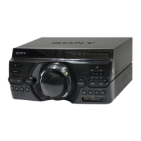
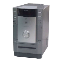
Photo: HCD-M80D
Inputs
AUDIO IN (TV) L/R:
Voltage 2 V, impedance
47 kilohms
TV (ARC):
Supported audio signal:
2-channel Linear PCM
MIC1:
Sensitivity 1 mV, impedance
10 kilohms
MIC2/GUITAR:
Sensitivity 1 mV, impedance
10 kilohms (When guitar mode is turned
off.)
Sensitivity 200 mV, impedance
250 kilohms (When guitar mode is
turned on.)
Outputs
HDMI OUT (TV) ARC:
Supported audio signal:
2-channel Linear PCM (up to
48 kHz), Dolby Digital
HDMI section
Connector:
Type A (19 pin)
Disc player section
System:
Compact disc and digital audio and
video system
Laser Diode Properties
Emission Duration: Continuous
Laser Output*: Less than 44.6 μW
* This output is the value measurement
at a distance of 200 mm from the
objective lens surface on the Optical
Pick-up Block with 7 mm aperture.
Frequency response:
20 Hz – 20 kHz
Video color system format:
Latin American model:
NTSC
Other models:
NTSC and PAL
USB section
Supported USB device:
Mass Storage Class
Maximum current:
1 A
(USB) port:
Type A
FM tuner section
FM stereo, FM superheterodyne tuner
Antenna:
FM lead antenna
Tuning range:
76 MHz - 108 MHz (100 kHz step)
(Brazilian model)
87.5 MHz – 108.0 MHz (50 kHz step)
(except Brazilian model)
BLUETOOTH section
Communication system:
BLUETOOTH Standard version 4.2
Output:
BLUETOOTH Standard Power Class 2
Maximum output power:
< 9.5 dBm
Maximum communication range:
Line of sight approx. 10 m
*1
Maximum number of devices to be registered
8 devices
Maximum number of simultaneous connection
(Multipoint)
3 devices
Frequency band:
2.4 GHz band (2.4000 GHz –
2.4835 GHz)
Modulation method:
FHSS (Freq Hopping Spread Spectrum)
Compatible BLUETOOTH profiles
*2
:
A2DP (Advanced Audio Distribution
Profile)
AVRCP (Audio Video Remote Control
Profile)
SPP (Serial Port Profile)
Supported codecs:
SBC (Subband Codec)
AAC (Advanced Audio Coding)
LDAC
*1
The actual range will vary depending on
factors such as obstacles between devices,
magnetic fields around a microwave oven,
static electricity, reception sensitivity,
antenna’s performance, operating system,
software application, etc.
*2
BLUETOOTH standard profiles indicate the
purpose of BLUETOOTH communication
between devices.
Supported audio formats
Supported bit rate and sampling frequencies:
MP3:
32/44.1/48 kHz, 32 kbps – 320 kbps
(VBR)
AAC:
44.1 kHz, 48 kbps – 320 kbps
(CBR/VBR)
WMA:
44.1 kHz, 48 kbps – 192 kbps
(CBR/VBR)
WAV:
44.1/48 kHz (16 bit)
– Continued on next page –
HCD-M40D/M60D/
M80D
Note:
Be sure to keep your PC used for service and
checking of this unit always updated with the
latest version of your anti-virus software.
In case a virus aff ected unit was found during
service, contact your Service Headquarters.


