Do you have a question about the Sony HCD-R550 and is the answer not in the manual?
Details tape player recording system and frequency response.
Covers FM and AM tuner sections, including tuning ranges.
Lists power requirements, consumption, dimensions, and accessories.
Precautions for handling optical pick-up blocks to prevent static damage.
Safety guidelines for checking laser diode emission.
Advice on reusing chip components and handling tantalum capacitors.
Guidelines for repairing flexible circuit boards, including temperature.
Procedures and limits for checking AC leakage.
Instructions for installing the rotary encoder and base unit.
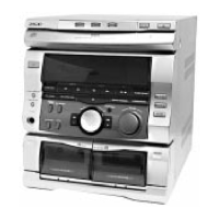
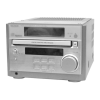
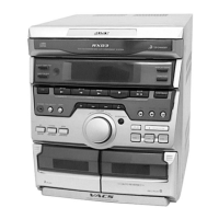
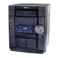
Identifies buttons and indicators on the front panel.
Procedure for changing the clock time when the power is on.
Instructions for disassembling the outer case of the unit.
Steps for disassembling the front panel assembly.
Procedure for disassembling the CD mechanism deck.
Clears all data and resets the unit to initial conditions.
Moves the pickup to a position durable to vibration for shipping.
Resets the unit while retaining preset data in memory.
Allows free control of the CD sled motor for cleaning or adjustment.
Switches the AM channel step between 9 kHz and 10 kHz.
Checks all LEDs, the indicator tube, and button functions.
Details display states and operation sequence for tape deck aging.
Describes the sequence of tape deck aging operations.
Details display states for CD aging mode.
Describes the sequence of CD aging operations.
Cleaning and demagnetizing precautions before adjustments.
Table showing torque specifications for various tape deck modes.
General precautions and setup for deck electrical adjustments.
Lists test tapes and their usage for adjustments.
Procedure for adjusting azimuth for both decks.
Procedure for checking and confirming the S-curve waveform.
Procedure for checking E-F balance using a 1-track jump.
Procedure for checking the RF signal level.
Procedure to check the RF PLL free-run frequency.
Diagram showing the location of various circuit boards in the unit.
Schematic diagram for the leaf switch section.
Schematic diagram for the CD switch section.
Exploded view of the case section with part numbers.
Exploded view of the front panel section with part numbers.
Exploded view of the chassis section with part numbers.
Exploded view of the CD mechanism deck section 1.
Exploded view of the CD mechanism deck section 2.
Exploded view of the base unit section.
Exploded view of the tape mechanism deck section 1.
Exploded view of the tape mechanism deck section 2.
List of capacitors used in the AC SEC and AUDIO sections.
Notes on resistors and abbreviations used in the parts list.
Notes on semiconductor notation and component identification.
| Type | Mini Hi-Fi Component System |
|---|---|
| Power Output | 100 W |
| Audio Channels | 2.0 |
| CD Player | Yes |
| Tuner | FM/AM |
| Cassette Deck | Yes |
| Remote Control | Yes |
| Bluetooth | No |
| USB Playback | No |
| Functions | CD, Cassette, Radio |