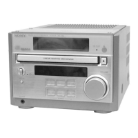
HCD-RB5
US Model
Canadian Model
AEP Model
UK Model
E Model
Australian Model
Chinese Model
SERVICE MANUAL
MICRO Hi-Fi COMPONENT SYSTEM
Model Name Using Similar Mechanism NEW
CD Mechanism Type CDM55C-K6BD38
Base Unit Name BU-K6BD38
Optical Pick-up Name KSM-213DCP
• This set is the Amplifier and CD player
section in CMT-RB5.
SPECIFICATIONS
CD player section
System Compact disc and digital audio
system
Laser Semiconductor laser (λ=780 nm)
Emission duration: continuous
Laser output MAX. 44.6 µW*
*This output is the value measured
at a distance of 200 mm from the
objective lens surface on the
Optical Pick-up Block with 7 mm
aperture.
Frequency response 2 Hz – 20 kHz
Tuner section
FM stereo, FM/AM superheterodyne tuner
FM tuner section
Tuning range
US, Canadian model: 87.5 – 108.0 MHz
(100 kHz step)
Other models: 87.5 – 108.0 MHz
(50 kHz step)
Antenna FM lead antenna
Antenna terminals 75 ohms unbalanced
Intermediate frequency 10.7 MHz
AM tuner section
Tuning range
US, Canadian model: 530 – 1,710 kHz
(with the interval set at 10 kHz)
531 – 1,710 kHz
(with the interval set at 9 kHz)
European model: 531 – 1,602 kHz
(with the interval set at 9 kHz)
Other models: 531 – 1,602 kHz
(with the interval set at 9 kHz)
530 – 1,710 kHz
(with the interval set at 10 kHz)
Antenna AM loop antenna
External antenna terminals
Intermediate frequency 450 kHz
General
Power requirements
US, Canadian model: 120 V AC, 60 Hz
European model: 230 V AC, 50/60 Hz
Australian model: 220 – 240 V AC, 50/60 Hz
Korea, Chinese model: 220 V AC, 50/60 Hz
Mexican model: 120 V AC, 60 Hz
Other models: 110 – 120 V or 220 – 240 V AC,
50/60 Hz
Adjustable with voltage selector
Power consumption
US, Canadian and Mexican models:
50 watts
Other models: 45 watts
Dimensions (w/h/d) Approx. 180 × 130 × 315 mm
incl. projecting parts and controls
Mass Approx. 4.0 kg
Supplied accessories Remote (1)
Size AA (R6) batteries (2)
AM loop antenna (1)
FM lead antenna (1)
Speaker cords (2)
Design and specifications are subject to change
without notice.
Main Unit
Amplifier section
For the U.S. model
AUDIO POWER SPECIFICATIONS
POWER OUTPUT AND TOTAL HARMONIC
DISTORTION:
With 4-ohm loads, both channels driven, from
120 – 10,000 Hz; rated 15 watts per channel
minimum RMS power, with no more than 10%
total harmonic distortion from 250 milliwatts to
rated output.
US, Canadian and Mexican models:
Continuous RMS power output (reference):
15 + 15 watts
(4 ohms at 1 kHz, 10% THD)
European and Australian models:
DIN power output (Rated):12 + 12 watts
(4 ohms at 1 kHz, DIN)
Continuous RMS power output (Reference):
15 + 15 watts
(4 ohms at 1 kHz,
10% THD)
Music power output (Reference):
28 + 28 watts
Other models:
The following measured at 220 V AC, 50/60 Hz
DIN power output (rated): 10 + 10 watts
(4 ohms at 1 kHz, DIN)
Continuous RMS power output (reference):
12 + 12 watts
(4 ohms at 1 kHz, 10% THD)
The following measured at 240 V AC, 50/60 Hz
DIN power output (rated): 12 + 12 watts
(4 ohms at 1 kHz, DIN)
Continuous RMS power output (reference):
15 + 15 watts
(4 ohms at 1 kHz, 10% THD)
Inputs
MD/VIDEO (AUDIO) IN (phono jacks):
voltage 500/250 mV, impedance
47 kilohms
Outputs
MD/VIDEO (AUDIO) OUT (phono jack):
voltage 250 mV, impedance
1 kilohm
PHONES (stereo minijack):
accepts headphones of 8 ohms or
more.
SPEAKER: accepts impedance of 4 to
16 ohms.
CD DIGITAL OUT OPTICAL:
Optical