EasyManua.ls Logo

Sony HCD-RV55 User Manual

Sony HCD-RV55
86 pages
To Next Page IconTo Next Page
Page #1 background imageLoading...
Page #1 background image
1
Ver 1.0 2004. 08
Model Name Using Similar Mechanism NEW
CD CD Mechanism Type CDM74-K4BD49
Section Base Unit Name BU-K4BD49
Optical Pick-up Name KSM-213DHAP
Model Name Using Similar Machanism
HCD-GN700
TAPE HCD-RG330
Section
Tape Mechanism Type
CWM43RR35
CWM43FF13
SERVICE MANUAL
E Model
HCD-RV22/RV55
Amplifier section
HCD-RV55
Front speaker
The following measured at AC 120, 127, 220, 240 V, 50/60 Hz
DIN power output (rated):
120 + 120 watts
(6 ohms at 1 kHz, DIN)
Continuous RMS power output (reference):
150 + 150 watts
(6 ohms at 1 kHz, 10% THD)
HCD-RV22
The following measured at AC 120, 127, 220, 240 V, 50/60 Hz
DIN power output (rated):
100 + 100 watts
(6 ohms at 1 kHz, DIN)
Continuous RMS power output (reference):
120 + 120 watts
(6 ohms at 1 kHz, 10% THD)
SPECIFICATIONS
Inputs
VIDEO/SAT IN (phono jacks) (HCD-RV55 only):
voltage 450/250 mV,
impedance 47 kilohms
GAME INPUT AUDIO L/R (phono jacks):
voltage 250 mV,
impedance 47 kilohms
GAME INPUT VIDEO (phono jack):
1 Vp-p, 75ohms
MIC (phone jack): sensitivity 1 mV,
impedance 10 kilohms
Outputs
PHONES (stereo phone jack):
accepts headphones of
8 ohms or more
VIDEO/SAT OUT (phono jacks) (HCD-RV55 only):
impedance 1 kilohm
Sony Corporation
Audio Group
Published by Sony Engineering Corporation
9-879-126-01
2004H04-1
© 2004. 08
– Continued on next page –
MINI Hi-Fi COMPONENT SYSTEM
(Photo: HCD-RV55)
HCD-RV22/RV55 are the tuner,
deck, CD and amplifier
section in MHC-RV22/RV55.
w
w
w
.
x
i
a
o
y
u
1
6
3
.
c
o
m
Q
Q
3
7
6
3
1
5
1
5
0
9
9
2
8
9
4
2
9
8
T
E
L
1
3
9
4
2
2
9
6
5
1
3
9
9
2
8
9
4
2
9
8
0
5
1
5
1
3
6
7
3
Q
Q
TEL 13942296513 QQ 376315150 892498299
http://www.xiaoyu163.com

Table of Contents

Question and Answer IconNeed help?

Do you have a question about the Sony HCD-RV55 and is the answer not in the manual?

Sony HCD-RV55 Specifications

General IconGeneral
TypeMini Hi-Fi System
Power Output100W
CD PlayerYes
TunerAM/FM
Cassette DeckYes
Audio Channels2.0
Remote ControlYes
Weight6.5 kg
Speakers2-way speaker system
InputsAuxiliary input
Cassette Deck TypeDual Cassette Deck

Summary

SERVICE MANUAL

HCD-RV22/RV55 Service Manual

Title of the service manual for the HCD-RV22/RV55.

System Overview

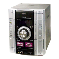
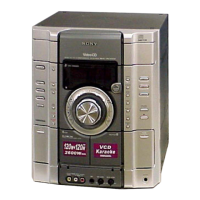
Defines the HCD-RV22/RV55 as tuner, deck, CD, and amplifier sections.

Specifications

Lists the technical specifications of the system.

Repair and Handling Precautions

Section 6 Diagrams

Section 1 Service Notes

Section 3 Disassembly Procedures

Section 4 Test Modes

Operational Modes

Aging and Panel Test Modes

Explains Aging Mode for operation checks and Panel Test Mode for component verification.

Test Modes and Error Codes

MC Test Mode and Version Display

Covers MC Test Mode for microprocessor checks and version display mode.

Error Code Displays

Details mechanism deck and CD error code display modes and their meanings.

Section 5 Electrical Adjustments

CD Section Adjustments

Details S-curve, traverse level, and RF level checks for CD adjustments.

CD Mechanism Printed Wiring Boards (1/2)

CD Mechanism Schematic Diagrams (1/2)

CD Mechanism Printed Wiring Boards (2/2)

CD Mechanism Schematic Diagrams (2/2)

VCD Connect Board Diagrams

Printed Wiring and Schematic Diagrams

Shows printed wiring and schematic diagrams for the VCD connect board.

VMP Section Printed Wiring Board

VMP Section Schematic Diagram (1/2)

VMP Section Schematic Diagram (2/2)

Main Section Schematic Diagram (1/2)

Main Section Schematic Diagram (2/2)

Main Section Printed Wiring Board

Panel Section Printed Wiring Boards

Panel Section Schematic Diagram (1/2)

Panel Section Schematic Diagram (2/2)

Jack Section Printed Wiring Boards

Jack Section Schematic Diagram

Power Section (RV22) Printed Wiring Board (1/2)

Power Section (RV22) Printed Wiring Board (2/2)

Power Section (RV22) Schematic Diagram

Power Section (RV55) Schematic Diagram

Power Section (RV55) Printed Wiring Board (1/2)

Power Section (RV55) Printed Wiring Board (2/2)

IC Block Diagrams

Main Board IC Pin Functions

IC101 BD3401KS2 Pin Functions

Details the pin functions of the IC101 BD3401KS2 on the main board.

IC201 BA3126N Pin Functions

Details the pin functions of the IC201 BA3126N on the main board.

IC371 BU2099FV Pin Functions

Details the pin functions of the IC371 BU2099FV on the main board.

VMP43GY Board IC Pin Functions

IC505 CXD1887R Pin Functions

Details the pin functions of IC505 CXD1887R on the VMP43GY board.

Main Board IC371 BU2099FV Pin Functions

Panel Board IC601 LC876964C-52S6-E Pin Functions

Section 7 Exploded Views

Section 8 Electrical Parts List

Related product manuals