Do you have a question about the Sony HCD-RV60 and is the answer not in the manual?
Details power output specifications for RV20, RV50, and RV60 models.
Lists various audio/video input and output specifications.
Details CD player mechanism and pick-up information.
Details tape deck mechanism types.
Describes speaker configurations, units, and dimensions.
Covers power requirements, consumption, dimensions, and mass.
Lists items included with the main unit.
Guidance on chip components, flexible PCBs, and optical pick-ups.
Precautions for laser emission checks and classification.
Procedure for setting and releasing the CD tray lock.
Lists models and corresponding part numbers for the back panel.
Details buttons on the RV20 main unit and their page references.
Details buttons on the RV20 remote control and their page references.
Details buttons on the RV50/RV60 main unit and their page references.
Details buttons on the RV50/RV60 remote control and their page references.
Covers case, CD door, front panel removal steps.
Covers CD mechanism, optical pick-up, BD board removal.
Covers panel, LED, remote, jack, main, power amp, video, SW, driver boards.
Covers motor (TB/LD) and sensor boards removal.
Details pin functions for system control ICs.
Visual map of component board placement.
Displays signal waveforms for key boards.
Component layout for the CD mechanism.
Electrical schematic for the CD mechanism.
Layout for additional CD mechanism components.
Electrical schematics for CD mechanism components.
Component layout for the video board.
Component layout for the video board's reverse side.
Electrical schematic for the video section.
Electrical schematic for the video section.
Component layout for the main board.
Electrical schematic for the main section.
Electrical schematic for the main section.
Electrical schematic for the main section.
Component layout for panel and LED boards.
Electrical schematic for the panel section.
Component layout for the jack board.
Electrical schematic for the jack section.
Component layout for the power amp board.
Electrical schematic for the power amp section.
Electrical schematic for the power amp section.
Component layout for the RV20 transformer board.
Component layout for the RV50 transformer board.
Component layout for the RV60 transformer board.
Electrical schematic for the transformer section.
Functional block diagram of IC102.
Functional block diagram of IC103.
Functional block diagrams of IC701 and IC712.
Functional block diagram of IC504.
Functional block diagram of IC506.
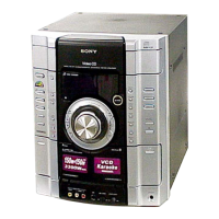
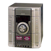
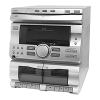
Diagram of main unit components and parts list.
Diagram of front panel components and parts list.
Diagram of front panel components and parts list.
Diagram of front panel components and parts list.
Diagram of main board components and parts list.
Diagram of CD mechanism components and parts list.
Diagram of CD mechanism components and parts list.
Diagram of optical pick-up components and parts list.
List of components for the BD board.
List of components for the driver board.
List of components for the driver board.
List of components for the jack board.
List of components for the jack board.
List of components for the main board.
List of components for the main board.
List of components for the main board.
List of components for the main board.
List of components for the main board.
List of components for the main board.
Lists components for motor and panel boards.
List of components for the panel board.
List of components for the panel board.
List of components for the panel board.
List of components for the power amp board.
List of components for the power amp board.
List of components for the power amp board.
List of components for the power amp board.
List of components for the power amp board.
Lists components for these boards.
List of components for the video board.
Lists components for stream LED boards.
Lists wires, decks, cords, and OP Assy.
Lists fuses, motors, transformers, and tuner pack.
Covers Cold Reset and CD Ship Mode procedures.
Covers Tuner Step Change and MD/Video input switching.
Covers CD tray lock and amplifier adjustment mode.
Checks CD and tape deck operation in parallel.
Describes the CD aging process sequence.
Describes the tape deck aging process sequence.
Checks indicators, LEDs, volume, and headphone functions.
Checks unit model, destination, and software version.
Displays error codes for the CD section.
Allows free movement of the CD sled motor.
Enables unlimited CD repeat playback.
Cleaning, demagnetizing, and tool usage guidelines.
Defines torque values for FWD, REV, and tension.
Procedures for tape deck adjustments.
Steps for aligning playback heads for L-CH and R-CH.
Verifies CD waveform symmetry and peak level.
Checks CD waveform levels during track jumping.
Verifies the RF signal level for CD playback.
Illustrates signal flow for CD and video processing.
Illustrates signal flow for tuner, tape, and panel functions.
Illustrates signal flow for audio amplification and power.
Lists version updates and their descriptions.
| Brand | Sony |
|---|---|
| Model | HCD-RV60 |
| Category | Stereo System |
| Language | English |