Do you have a question about the Sony HCD-R700 and is the answer not in the manual?
Procedures for safely handling the optical pick-up block to prevent electrostatic damage.
Guidelines for safely checking the laser diode emission point on the optical pick-up block.
Notes on replacing chip components, including warnings about reuse and heat sensitivity.
Precautions for repairing flexible circuit boards, focusing on soldering iron temperature and conductor care.
General warnings about incorrect adjustments leading to hazardous radiation exposure.
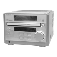
Identifies and describes the functions of various buttons, knobs, and jacks on the unit.
Step-by-step instructions for setting the clock on the unit using the jog dial and buttons.
Procedure for removing the outer case of the unit, detailing screw locations and panel removal.
Steps for detaching the front panel assembly, including disc tray and wire disconnections.
Procedure for removing the tape mechanism deck, detailing lid opening and screw removal.
Steps for detaching the CD mechanism deck, including screw removal and connector disconnection.
Procedure for accessing and removing the main board, detailing screw and connector removal.
Clears all data in RAM to initial conditions, used when returning the set to the customer.
Moves the pickup to a durable position for vibration, used after repair before customer return.
Resets the set with preset data kept in memory, similar to power cycling.
Allows free operation of the CD sled motor, useful for pickup cleaning.
Procedure to switch the AM tuner channel step between 9 kHz and 10 kHz.
Activates all LEDs and the fluorescent indicator tube for key function testing.
Performs operation checks on the CD and tape deck sections automatically.
Details the torque specifications for various tape deck mechanisms like FWD, REV, FF/REW.
Procedures for demagnetizing heads and adjusting azimuth, tape speed, and playback levels.
Procedures for adjusting AM and FM tuned levels and FM polar characteristics.
Procedures for checking CD section performance like S-curve and RF signal levels.
Illustrates the physical layout and names of all circuit boards within the unit.
High-level functional diagrams showing signal paths and major components for various sections.
Detailed electrical schematics and printed wiring board layouts for all unit sections.
Detailed pin-out and function descriptions for key integrated circuits used in the system.
Visual representations of the internal logic and functions of specific integrated circuits.
Illustrates the parts and assembly of the main unit case.
Details the assembly of the front panel, including buttons, displays, and associated parts.
Shows the main chassis components and their arrangement, including board mounting.
Illustrates the parts and assembly of the CD mechanism deck (Section 1 and 2).
Details the assembly of the CD base unit (BU-5BD29AL), including optical pick-up.
Illustrates the parts and assembly of the tape mechanism deck (Section 1 and 2).
Comprehensive list of electronic components for the Audio board.
Comprehensive list of electronic components for the Main board.
Comprehensive list of electronic components for the HP and Leaf SW boards.
Comprehensive list of electronic components for the Panel board.
Comprehensive list of electronic components for the Power Amp board.
Comprehensive list of electronic components for the TCB board.
Comprehensive list of electronic components for the Transformer section.
| CD Player | Yes |
|---|---|
| Bluetooth | No |
| USB Playback | No |
| Dimensions | 335 x 360 x 250 mm |
| Weight | 6.2 kg |
| Audio Channels | 2.0 |
| Cassette Deck | Yes |
| Remote Control | Yes |
| Tuner | AM/FM |
| Functions | CD, Tuner, Cassette |
| Type | Mini Hi-Fi Component System |
| Power Output | 100W + 100W (RMS) |