Do you have a question about the Sony HCD-RV999D and is the answer not in the manual?
| Remote Control | Yes |
|---|---|
| Audio Channels | 2.0 |
| USB Playback | No |
| Bluetooth | No |
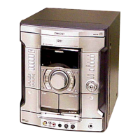
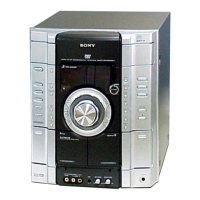
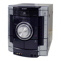
| Type | Mini Hi-Fi System |
| Functions | CD player, cassette deck |
| Tuner Bands | AM/FM |
Details product specifications including inputs and outputs.
Details the position of the Compact Disc Mechanism for service.
Outlines the procedure to determine the status of the optical pick-up block.
Details the GC Test Mode for checking functions like LEDs and volume.
Enables testing of Amplifier, Tuner, and Tape sections.
Used for operation check and aging of the tape deck section.
Covers sequences for DVD section aging and error history.
Allows easy diagnosis and adjustment using on-screen display.
Performs detailed checks of system controller operations.
Automates the adjustment of disc playback for different types.
Allows manual control and adjustment of each servo.
Function to select or automatically detect the disc type.
Controls servo on/off for replay and adjustment.
Manually adjusts items not stored in EEPROM.
Automatically adjusts EEPROM parameters for optimal performance.
Displays error rates for disc reading performance.
Shows historical error data for the mechanism deck.
Details torque specifications for various modes and measurements.
Covers demagnetization and adjustment of record/playback heads.
Procedure for checking and adjusting video signal level.
Refers to decision criteria for optical pick-up block pass/fail.
Re-adjusts the servo circuit after component replacement.
Adjustment procedure for tape head azimuth for optimal sound.
Illustrates the signal flow for the DVD Digital Signal Processor section.