EasyManua.ls Logo

Sony HCD-RV777D User Manual

Sony HCD-RV777D
120 pages
To Next Page IconTo Next Page
Page #1 background imageLoading...
Page #1 background image
1
Ver 1.0 2004. 06
DVD
Model Name Using Similar Mechanism NEW
Section
DVD Mechanism Type CDM74S-DVBU62
Optical Pick-up Name DBU-3
Tape Deck Model Name Using Similar Machanism HCD-RV660D/RV990D
Section Tape Transport Mechanism Type CWM43RR-35
SERVICE MANUAL
E Model
Australian Model
HCD-RV777D/RV888D/RV999D
Amplifier section
HCD-RV999D
The following measured at AC 120, 127, 220, 230 – 240 V,
50/60 Hz
Continuous RMS power output (reference)
Front speaker: 100 + 100 watts
(6 ohms at 1 kHz, 10%
THD)
Center speaker: 40 watts (6 ohms at 1 kHz,
10% THD)
Surround speaker: 40 + 40 watts
(6 ohms at 1 kHz, 10%
THD)
Sub woofer: 110 watts (4 ohms at
1 kHz, 10% THD)
HCD-RV888D
The following measured at AC 120, 127, 220, 230 – 240 V,
50/60 Hz
Continuous RMS power output (reference)
Front speaker: 100 + 100 watts
(6 ohms at 1 kHz, 10%
THD)
Center speaker: 40 watts (6 ohms at 1 kHz,
10% THD)
Surround speaker: 40 + 40 watts
(6 ohms at 1 kHz, 10%
THD)
HCD-RV777D
The following measured at AC 120, 127, 220, 230 – 240 V,
50/60 Hz
Continuous RMS power output (reference)
100 + 100 watts
(6 ohms at 1 kHz, 10%
THD)
SPECIFICATIONS
Inputs
VIDEO/SAT IN (audio) (phono jacks):
voltage 450/250 mV,
impedance 47 kilohms
GAME INPUT VIDEO (phono jack):
1 Vp-p, 75 ohms
GAME INPUT AUDIO (phono jacks):
voltage 250 mV,
impedance 47 kilohms
MIC (phone jack): sensitivity 1 mV,
impedance 10 kilohms
Outputs
VIDEO/SAT OUT (audio) (phono jacks):
voltage 250 mV,
impedance 1 kilohm
VIDEO OUT (phono jack):
max. output level
1 Vp-p, unbalanced, Sync
negative, load impedance
75 ohms
S-VIDEO OUT (4-pin/mini-DIN jack):
Y: 1 Vp-p, unbalanced,
Sync negative,
C: 0.286 Vp-p, load
impedance 75 ohms
COMPONENT VIDEO OUT:
Y: 1 Vp-p, 75 ohms
PB, PR: 0.7 Vp-p, 75 ohms
Sony Corporation
Home Audio Company
Published by Sony Engineering Corporation
9-877-866-01
2004F04-1
© 2004. 06
– Continued on next page –
DVD DECK RECEIVER
(Photo: HCD-RV888D)
HCD-RV777D/RV888D/RV999D are
the tuner, deck, DVD and amplifier
section in MHC-RV777D/RV888D/
RV999D.
w
w
w
.
x
i
a
o
y
u
1
6
3
.
c
o
m
Q
Q
3
7
6
3
1
5
1
5
0
9
9
2
8
9
4
2
9
8
T
E
L
1
3
9
4
2
2
9
6
5
1
3
9
9
2
8
9
4
2
9
8
0
5
1
5
1
3
6
7
3
Q
Q
TEL 13942296513 QQ 376315150 892498299
http://www.xiaoyu163.com

Table of Contents

Question and Answer IconNeed help?

Do you have a question about the Sony HCD-RV777D and is the answer not in the manual?

Sony HCD-RV777D Specifications

General IconGeneral
CD PlayerYes
BluetoothNo
Remote ControlYes
Power Output100W
FunctionsCD, Radio
Output Power100W
MP3 PlaybackYes
WMA PlaybackYes

Summary

Amplifier Section

Tuner and General Specifications

General Unit Specifications and Safety

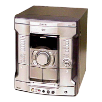
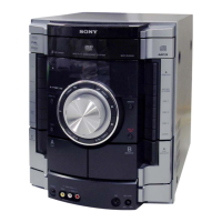
Details on power supply, dimensions, accessories, and critical component safety.

Service Notes and Precautions

Service Notes and General Information

Disassembly Procedures

Test Mode Operations

Basic Test Mode Functions

Procedures for cold reset, tuner step change, video/MD function, and disc tray lock.

GC Test Mode and Checks

Details on GC Test Mode, checking LEDs, keyboard, volume, and headphone status.

Test Mode Procedures and Sequences

MC Test Mode Operations

Procedures for checking amplifier, tuner, and tape operations in MC Test Mode.

Aging Mode Sequences

Aging mode sequences for tape deck and DVD sections to check performance.

Test Mode Execution and Menus

DVD OSD Test Mode Description

General description of the DVD OSD test mode for diagnosis and adjustment.

Starting and Operating Test Modes

Instructions on how to start and operate various test modes, including Syscon Diagnosis.

Test Mode - Checking Methods

Drive Auto Adjustment Procedure

Steps for performing drive auto adjustment for DVD-SL, CD, and DVD-DL discs.

Disc Type and Servo Adjustment

Disc Type Adjustment Steps

Detailed steps for adjusting disc type for DVD-SL, CD, and DVD-DL discs.

Servo Control and Manual Operations

Instructions for controlling servo on/off for replay and performing manual operations.

Test Mode - Adjustments and Checks

Track/Layer Jump and Non-EEPROM Adjustments

Procedures for track/layer jump on DVD discs and non-EEPROM write adjustments.

EEPROM Write Adjust and Memory Check

Steps for EEPROM write adjustments and checking memory contents.

Test Mode - Diagnostics

Disc Check Memory and Error Rate Display

Procedures for checking disc memory and displaying error rates.

Mecha Aging and Emergency History

Steps for mecha aging and accessing emergency history information.

Test Mode - History and Error Codes

Clearing History Information

Instructions for clearing laser hours, emergency history, and initializing set up data.

Mecha Error History Codes

Explanation of mecha error history codes and their meanings.

Test Mode - Version and Video Adjustment

Version Information Display

How to display ROM version and region code for system controllers.

Video Level Adjustment Procedure

Procedure for adjusting video level using color bars for NTSC standard compliance.

Mechanical Adjustments

Precautions for Mechanical Adjustments

General precautions to follow before and during mechanical adjustments.

Torque Measurement Specifications

Table of torque meter readings and specifications for various modes.

Electrical Adjustments

Video Section Adjustment

Procedure for checking video signal level to meet NTSC standards.

Deck Section Adjustments

Steps for demagnetizing heads and performing azimuth adjustment.

DVD Section - Pass/Fail and Test Discs

Criteria for DVD section pass/fail and list of required test discs.

Auto Servo Adjustment Procedure

Necessity and procedure for re-adjusting servo circuit after part replacement.

Playback Head Adjustment

Playback Head Azimuth Adjustment

Procedure for adjusting playback head azimuth for L-CH and R-CH output peaks.

Block Diagrams - DVD System

DVD DSP Section Block Diagram

Schematic block diagram illustrating the DVD DSP section.

DAC Section Block Diagram

Block diagram detailing the DAC section and its connections.

Main Section Block Diagram

Block diagram showing the main section's signal paths and components.

DVD SYS Section Block Diagram

Block diagram illustrating the DVD SYS section.

Printed Wiring Board Layouts

Schematic Diagrams - DMB07 Section

Schematic Diagrams - Main Section

Schematic Diagrams - Amplifier Sections

Front Amp Section Schematic

Schematic diagram illustrating the front amplifier section's circuitry.

Schematic Diagrams - Surround Amp

Surround Amp Section Schematic

Schematic diagram detailing the surround amplifier section's circuits.

Schematic Diagrams - Input/Output Sections

Jack Section Schematic

Circuit diagram for the Jack Board, detailing input/output connections.

Schematic Diagrams - Power and Transformer Sections

Trans Section Schematic

Circuit diagram for the Trans Section, including transformer and power supply connections.

Schematic Diagrams - Sub Transformer Section

Sub Trans Section Schematic

Circuit diagram for the Sub Trans Section, showing power supply and transformer connections.

IC Block Diagrams

Exploded Views - Unit Assembly

Electrical Parts List

Related product manuals