2
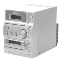
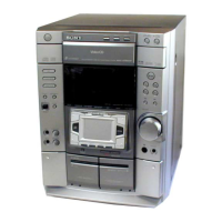
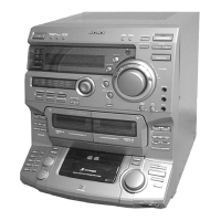
HCD-VP100
General
Power requirements 110 - 120 V or 220 -
240 V AC , 50/60 Hz
Adjustable with voltage
selector
Power consumption 75 W
Dimensions (w/h/d) Approx. 190 × 252 ×
345 mm incl. projecting
parts and controls
Mass Approx. 5.6 kg
Supplied accessories Remote commander (1)
AM loop antenna (1)
FM wire antenna (1)
Batteries (2)
Video connecting cord (1)
Design and specifications are subject to change
without notice.
AM tuner section
Tuning range
Middle Eastern and Philippine models:
531 - 1,602 kHz
(with the tuning interval
set at 9 kHz)
Other models: 530 - 1,710 kHz
(with the tuning interval
set at 10 kHz)
531 - 1,602 kHz
(with the tuning interval
set at 9 kHz)
Antenna AM loop antenna, external
antenna terminal
Intermediate frequency 450 kHz
Tuner section
FM stereo, FM/AM superheterodyne tuner
FM tuner section
Tuning range 87.5 - 108.0 MHz
(50-kHz step)
Antenna FM wire antenna
Antenna terminals 75 ohm unbalanced
Intermediate frequency 10.7 MHz
TABLE OF CONTENTS
1. GENERAL
Location of Controls ....................................................... 4
Setting the Time .............................................................. 5
2. DISASSEMBLY
2-1. Disassembly Flow ........................................................... 7
2-2. Cover (Upper) ................................................................. 8
2-3. CD Lid ............................................................................. 8
2-4. Front Panel Section ......................................................... 9
2-5. Tape Mechanism Deck .................................................... 9
2-6. CD Mechanism Deck (CDM55F-K6BD42A),
MPEG Board ................................................................... 10
2-7. Base Unit (BU-K6BD42A)............................................. 10
2-8. Loading Board................................................................. 11
2-9. Cam (CDM55) ................................................................ 11
3. TEST MODE.............................................................. 12
4. ELECTRICAL ADJUSTMENTS
Deck Section ................................................................... 13
CD Section ...................................................................... 13
5. DIAGRAMS
5-1. Block Diagram – CD SERVO Section – ........................ 14
5-2. Block Diagram – MAIN Section – ................................. 15
5-3. Block Diagram
– DISPLAY/POWER SUPPLY Section – ...................... 16
5-4. Note for Printed Wiring Boards and
Schematic Diagrams ....................................................... 17
5-5. Printed Wiring Board – CD Board – .............................. 18
5-6. Schematic Diagram – CD Board – ................................. 19
5-7. Printed Wiring Board – TC Board – ............................... 20
5-8. Schematic Diagram – TC Board – .................................. 21
5-9. Schematic Diagram
– MAIN (1/2)/LOADING Boards – ............................... 22
5-10. Schematic Diagram – MAIN Board (2/2) – ................... 23
5-11. Printed Wiring Boards
– MAIN/LOADING Boards – ....................................... 24
5-12. Printed Wiring Boards
– SWITCH/TC SWITCH/PRISM Boards – ................... 26
5-13. Schematic Diagram
– SWITCH/TC SWITCH/PRISM Boards – ................... 27
5-14. IC Pin Function Description ........................................... 28
5-15. Printed Wiring Boards
– LCD/HEADPHONE/DIGITAL Boards – ................... 29
5-16. Schematic Diagram
– LCD/HEADPHONE/DIGITAL Boards – ................... 29
5-17. Printed Wiring Board – POWER Board – ...................... 30
5-18. Schematic Diagram – POWER Board – ......................... 31
6. EXPLODED VIEWS
6-1. Cover Section .................................................................. 34
6-2. Front Panel Section ......................................................... 35
6-3. Chassis Section ............................................................... 36
6-4. CD Mechanism Deck (CDM55F-K6BD42A)................ 37
6-5. Base Unit (BU-K6BD42A)............................................. 38
7. ELECTRICAL PARTS LIST ............................... 39
w
w
w
.
x
i
a
o
y
u
1
6
3
.
c
o
m
Q
Q
3
7
6
3
1
5
1
5
0
9
9
2
8
9
4
2
9
8
T
E
L
1
3
9
4
2
2
9
6
5
1
3
9
9
2
8
9
4
2
9
8
0
5
1
5
1
3
6
7
3
Q
Q
TEL 13942296513 QQ 376315150 892498299
TEL 13942296513 QQ 376315150 892498299
http://www.xiaoyu163.com
http://www.xiaoyu163.com