Do you have a question about the Sony HCD-VR50 and is the answer not in the manual?
Specifies the rated power output according to DIN standards.
Details the continuous RMS power output for reference.
Procedure to clear all data and reset the unit to initial conditions.
Resets the unit with preset data stored, similar to power cycling.
Procedure for disassembling the front panel assembly.
Steps for removing the main board from the unit.
Mode for outputting color bars and audio signals for video CD signal check.
Sets the reference level for deck section electrical adjustments.
Procedure for adjusting head azimuth using a test tape.
Method for adjusting tape playback speed for Deck B using test modes.
Procedure to adjust playback levels for both decks using a test tape.
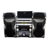
| Audio Channels | 2.0 |
|---|---|
| Remote Control | Yes |
| Tuner Bands | AM/FM |
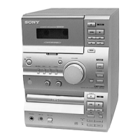
| Cassette Deck | Yes |
| Dimensions (W x H x D) | 280 x 280 x 280 mm |
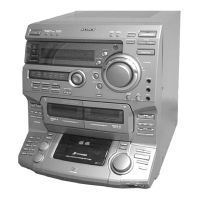
| Type | Mini Hi-Fi Component System |
| Functions | CD, Cassette, Radio |