Do you have a question about the Sony HCD-VX8 and is the answer not in the manual?
Details of power output, inputs, and outputs for the amplifier circuit.
Specifications for the CD player, including laser, wavelength, response, and noise ratio.
FM/AM superheterodyne tuner specifications, tuning ranges, and antenna details.
Procedure for opening the disc tray when the power switch is off.
Information about the CD-TEXT display function and its limitations.
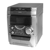
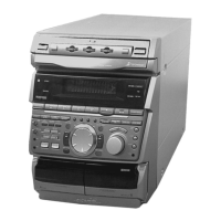
Identifies all buttons, knobs, jacks, and indicators on the front panel.
Steps to detach the front panel and access the video board.
Instructions for removing the cassette lid and tape mechanism assembly.
Procedure for removing the disc tray from the unit.
Service modes for resetting memory and preparing for delivery.
Service modes for CD sled motor control and AM tuner step adjustment.
Mode to test all LEDs and the fluorescent indicator tube.
Test mode for outputting color bars and audio for video signal check.
Specifies torque values for various mechanical parts during adjustment.
Procedure for adjusting the head azimuth for optimal audio playback and recording.
Steps to adjust tape speed for both normal and double speed modes.
Process for adjusting recording bias levels on the tape deck.
Illustrates the physical placement of all circuit boards within the unit.
High-level diagrams showing functional blocks of CD, Video, and Deck sections.
Detailed circuit schematics for the Main section of the unit.
Layout diagrams showing component placement on CD, Deck, and Video PCBs.
Exploded diagram showing the main external casing components.
Exploded diagram detailing the front panel parts and their assembly.
Exploded views of the CD mechanism deck components.
List of electrical components for the audio board.
Comprehensive list of components for the Main board, including diodes and connectors.
Parts list for components on the Trans and Video boards.
| CD Player | Yes |
|---|---|
| Tuner | Yes |
| Cassette Deck | Yes |
| Cassette Deck Type | Dual |
| USB Port | No |
| Functions | CD, Tuner, Cassette |
| Speaker Type | 2-way |
| Speakers | Included |