EasyManua.ls Logo

Sony HCD-VX222 User Manual

Sony HCD-VX222
70 pages
To Next Page IconTo Next Page
Page #1 background imageLoading...
Page #1 background image
HCD-VX222
E Model
SERVICE MANUAL
MINI HI-FI COMPONENT SYSTEM
— Continued on next page —
SPECIFICATIONS
HCD-VX222 is the tuner, deck, CD
and amplifier section in MHC-
VX222.
Ver 1.2 2001.09
9-873-210-03
2001I0200-1
© 2001. 9
Sony Corporation
Home Audio Company
Shinagawa Tec Service Manual Production Group
Model Name Using Similar Mechanism NEW
CD CD Mechanism Type CDM58B-K6BD37A
Section Base Unit Name BU-K6BD37A
Optical Pick-up Name KSM-213DCP/Z-NP
Tape deck
Model Name Using Similar Mechanism HCD-DX20/RG30
Section
Amplifier section
The following measured at AC 120, 220, 240 V
50/60 Hz
DIN power output (rated) 50 + 50 watts
(6 ohms at 1 kHz, DIN)
Continuous RMS power output (reference)
60 + 60 watts (6 ohms at
1 kHz, 10% THD)
Inputs
MD/VIDEO (AUDIO) IN (phono jacks):
voltage 450/250 mV,
impedance 47 kilohms
GAME (AUDIO) IN (phono jack):
voltage 450 mV,
impedance 47 kilohms
MIC 1/2 (mini jack): sensitivity 1 mV,
impedance 10 kilohms
Outputs
MD/VIDEO (AUDIO) OUT (phono jacks):
voltage 250 mV
impedance 1 kilohms
VIDEO OUT (phono jack):
max. output level
1Vp-p, unbalanced, Sync
negative, load impedance
75 ohms
S-VIDEO OUT (4-pin/mini-DIN jack):
Y: 1Vp-p, unbalanced,
Sync negative,
C: 0.286Vp-p,
load impedance 75 ohms
PHONES (stereo mini jack):
accepts headphones of
8 ohms or more
SPEAKER: accepts impedance of 6 to
16 ohms
Question and Answer IconNeed help?

Do you have a question about the Sony HCD-VX222 and is the answer not in the manual?

Sony HCD-VX222 Specifications

General IconGeneral
CD PlayerYes
Radio TunerYes
BluetoothNo
USB PortNo
Single DiscYes
Remote ControlYes
Power Output50W
FunctionsCD, Radio
Output Power50W
TunerFM/AM
Speakers2

Summary

SPECIFICATIONS

Amplifier section

Detailed specifications for the amplifier section, including power output and inputs.

Outputs

Details on audio and video outputs, including voltage levels and impedance.

Inputs

Specifications for audio inputs like MD/VIDEO, GAME, and MIC.

SERVICE NOTE

Removing the Panel Board and Key Board

Procedure for detaching the panel and key boards, including notes on installation.

GENERAL

Parts Identification - Main unit

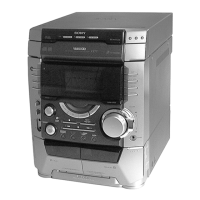
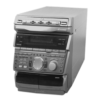
Lists and diagrams identifying various parts of the main unit.

Setting the time

DISASSEMBLY

CASE (SIDE-R, SIDE-L, TOP)

Instructions for disassembling the outer casing parts of the unit.

CD MECHANISM DECK SECTION

CD DDOR

Procedure for accessing and handling the CD door mechanism.

CD MECHANISM DECK, FRONT PANEL SECTION, CHASSIS SECTION

Steps for disassembling the CD mechanism, front panel, and chassis.

SUB TRANS BOARD, VIDEO OUT BOARD, BACK PANEL, POWER TRANSFORMER (TRANS BOARD)

MAIN BOARD, POWER AMP BOARD

VIDEO BOARD, BASE UNIT, BD BOARD

TEST MODE

MC Cold Reset

Clears all data including preset data stored in RAM.

CD Service Mode

Allows free running of the CD sled motor for cleaning.

GC Test Mode

Checks software version, FL tube, LED, keyboard, headphone and volume.

MC Test Mode

Microprocessor version display

Displays microprocessor version numbers, model name, and destination.

Aging Mode

Aging Mode in CD section

Checks CD section operation, displays status and error history.

Error display

Details error codes and their meanings for mechanism and disc errors.

ELECTRICAL ADJUSTMENTS

FM Tuned Level Adjustment

Adjusts the FM signal generator output level for proper tuning.

CD SECTION

Checks and adjustments specific to the CD playback mechanism.

S-Curve Check

Confirms symmetrical S-curve waveform for focus/tracking.

E-F Balance (1 Track jump) Check

RF PLL Free-run Frequency Check

Checks the free-run frequency of the RF PLL circuit.

DIAGRAMS

Notes on Schematic Diagram

General notes regarding schematic diagrams and component identification.

CIRCUIT BOARD LOCATION

WAVEFORMS

Illustrations and descriptions of various signal waveforms for different boards.

BLOCK DIAGRAMS TUNER SECTION

MAIN SECTION

VIDEO SECTION

PRINTED WIRING BOARD - DRIVER SECTION

PRINTED WIRING BOARD - BD SECTION

SCHEMATIC DIAGRAM - BD SECTION

PRINTED WIRING BOARD - MAIN SECTION

SCHEMATIC DIAGRAM - MAIN SECTION (1/5)

PRINTED WIRING BOARD - POWER AMP SECTION

SCHEMATIC DIAGRAM - POWER AMP SECTION

PRINTED WIRING BOARD - PANEL SECTION

SCHEMATIC DIAGRAM - PANEL SECTION

PRINTED WIRING BOARD - TRANS SECTION

SCHEMATIC DIAGRAM - TRANS SECTION

PRINTED WIRING BOARD - VIDEO CD SECTION

SCHEMATIC DIAGRAM - VIDEO CD SECTION (1/2)

IC PIN FUNCTION DESCRIPTION

MAIN BOARD (4/5) IC401 M30622MAA-A98FP (MASTER CONTROL)

Pin details for the Master Control IC, detailing function and I/O.

VIDEO BOARD IC502 M30620MCA-B22FP (CD MECHANISM CONTROLLER)

IC BLOCK DIAGRAMS

IC101 CXD3008Q (BD BOARD)

Block diagram for the BD board's main IC, showing internal functions.

EXPLODED VIEWS

MAIN SECTION

Exploded view of the main assembly, showing major component placements.

FRONT PANEL SECTION

CHASSIS SECTION

CD MECHANISM DECK SECTION

ELECTRICAL PARTS LIST

ADDRESS SENOR BD

List of electronic components for the Address Sensor Board.

REVISION HISTORY

Related product manuals