– 12 –
SECTION 4
TEST MODE
VIDEO CD COLOR-BARS MODE
On this mode, the data of the color-bars signal as a picture signal and the 1kHz sine wave signal as a sound signal are output by the
mechanism control microcomputer (IC502) for video CD signal check. When measurement of the voltage and waveform on the VIDEO
board, perform it in this mode.
For reference, the color-bars signal can be observed at J302 (VIDEO OUT) and the sound signal can be observed at J101 (VIDEO/MD
(AUDIO) OUT) using an oscilloscope.
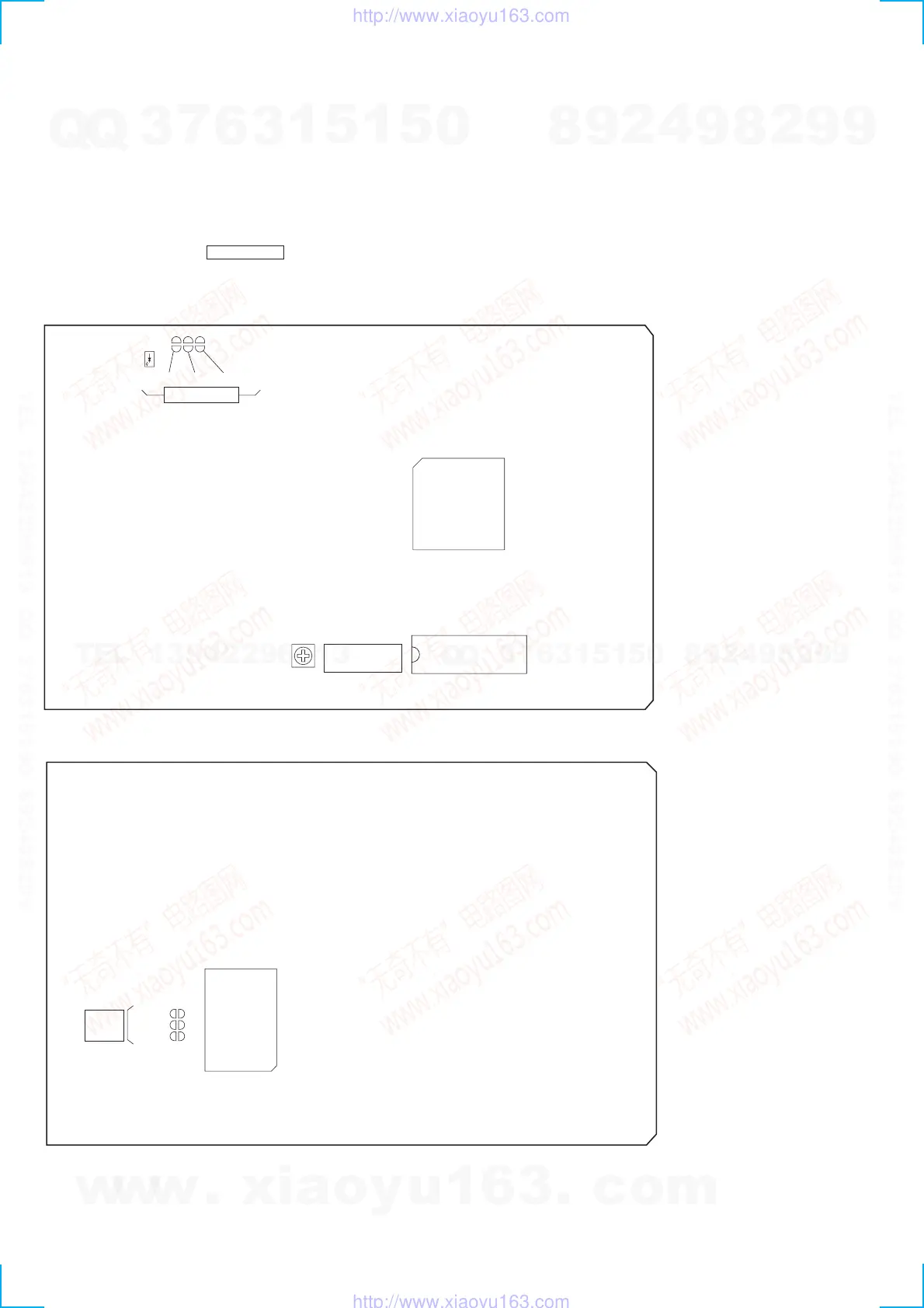
1. Connect the lead wire to both ends of the land of SL503 of the VIDEO board.
2. Turn the power on. Press FUNCTION button to select CD.
3. After 2 or 3 seconds later, connect the lead wire.
4. After measuring, remove the lead wire connected.
[VIDEO BOARD] (SIDE A)
[VIDEO BOARD] (SIDE B)
SL501
D502
SL502
IC507
IC505
CT503
SL503
TEST MODE
VIDEO
FREQUENCY
SL501
IC502
SL502
SL503
TEST
MODE
w
w
w
.
x
i
a
o
y
u
1
6
3
.
c
o
m
Q
Q
3
7
6
3
1
5
1
5
0
9
9
2
8
9
4
2
9
8
T
E
L
1
3
9
4
2
2
9
6
5
1
3
9
9
2
8
9
4
2
9
8
0
5
1
5
1
3
6
7
3
Q
Q
TEL 13942296513 QQ 376315150 892498299
TEL 13942296513 QQ 376315150 892498299
http://www.xiaoyu163.com
http://www.xiaoyu163.com