EasyManua.ls Logo

Sony HCD-V707 User Manual

Sony HCD-V707
81 pages
To Next Page IconTo Next Page
Page #1 background imageLoading...
Page #1 background image
MINI Hi-Fi COMPONENT SYSTEM
MICROFILM
SPECIFICATIONS
SERVICE MANUAL
HCD-V707
HCD-V707 is the tuner, deck, Video CD and
amplifier section in MHC-V707.
E Model
Chinese Model
Tourist Model
CD
Section
Tape deck
Section
Model Name Using Similar Mechanism HCD-V4500
CD Mechanism Type
CDM38L-5BD21AL
Base Unit Name BU-5BD21AL
Optical Pick-up Name
KSS-213D/Q-NP
Model Name Using Similar Mechanism HCD-H881
Tape Transport Mechanism Type TCM-220WR2F
– Continued on next page –
* Dolby noise reduction manufactured
under license from Dolby Laboratories
Licensing Corporation.
“DOLBY” and the double-D symbol a
are trademarks of Dolby Laboratories
Licensing Corporation.
w
w
w
.
x
i
a
o
y
u
1
6
3
.
c
o
m
Q
Q
3
7
6
3
1
5
1
5
0
9
9
2
8
9
4
2
9
8
T
E
L
1
3
9
4
2
2
9
6
5
1
3
9
9
2
8
9
4
2
9
8
0
5
1
5
1
3
6
7
3
Q
Q
TEL 13942296513 QQ 376315150 892498299
http://www.xiaoyu163.com

Table of Contents

Question and Answer IconNeed help?

Do you have a question about the Sony HCD-V707 and is the answer not in the manual?

Sony HCD-V707 Specifications

General IconGeneral
BrandSony
ModelHCD-V707
CategoryStereo System
LanguageEnglish

Summary

Specifications

Servicing Notes

Notes on Handling the Optical Pick-up Block or Base Unit

Precautions for handling sensitive optical pick-up components to prevent damage from static electricity.

Notes on Laser Diode Emission Check

Guidelines for safely checking laser diode emission from the optical pick-up block.

Laser Diode and Focus Search Operation Check

Procedure for checking laser diode and focus search operation in the CD section.

Notes on Chip Component Replacement

Important considerations for replacing surface-mount chip components, especially tantalum capacitors.

Flexible Circuit Board Repairing

Recommendations for repairing flexible circuit boards, including soldering temperature and force application.

Section 1 General

Location of Controls - Front Panel

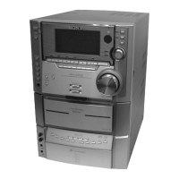
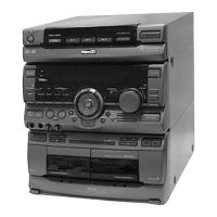
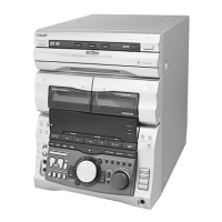
Diagram and labels identifying all controls and connectors on the front panel of the unit.

Section 3 Test Mode

MC Cold Reset

Clears all RAM data including preset data to initial conditions. Used when returning the set to the customer.

CD Delivery Mode

Moves the pick-up to a position durable to vibration. Used when returning the set after repair.

MC Hot Reset

Resets the set with preset data kept in memory. Functions like plugging/unplugging the power cord.

Sled Servo Mode

Allows free movement of the CD sled motor. Useful for cleaning the pick-up.

Change-over of Function Name

Allows changing the external input terminal name to 'VIDEO' or 'MD'.

Aging Mode

Section 4 Mechanical Adjustments

CD Section

E-F Balance Check

Video Section

Section 6 Diagrams

Section 7 Exploded Views

Section 8 Electrical Parts List

Related product manuals