EasyManua.ls Logo

Sony HCD-V818 Service Manual

Sony HCD-V818
92 pages
To Next Page IconTo Next Page
Page #1 background imageLoading...
Page #1 background image
– 1 –
E Model
SPECIFICATIONS
SERVICE MANUAL
COMPACT DISC DECK RECEIVER
— Continued on next page —
MICROFILM
HCD-V818
HCD-V818 is the tuner, deck, Video CD
and amplifier section in MHC-V818.
Model Name Using Similar Mechanism HCD-V800
CD Mechanism Type CDM38L-5BD24AL
Base Unit Type BU-5BD24AL
Optical Pick-up Type KSS-213D/Q-NP
Model Name Using Similar Mechanism HCD-GRX8/R800/RX88/RX99
Tape Transport Mechanism Type TCM-230AWR1
TCM-230PWR1
CD
SECTION
TAPE
DECK
SECTION

Table of Contents

Question and Answer IconNeed help?

Do you have a question about the Sony HCD-V818 and is the answer not in the manual?

Sony HCD-V818 Specifications

General IconGeneral
BrandSony
ModelHCD-V818
CategoryStereo System
LanguageEnglish

Summary

SPECIFICATIONS

Amplifier section

Details on power, inputs, and outputs.

VIDEO CD/CD Player Section

Details on laser, system, and output specifications.

Tuner section

Details on tuner wavelength and frequency response.

Tape player section

Details on tape recording system and frequency response.

SELF DIAGNOSIS

Lighting of D502 Indicator

Describes D502 indicator function for diagnosing circuit conditions.

General Service Notes

Chip Component Replacement

Guidelines for safely replacing chip components.

Flexible Circuit Board Repair

Precautions for repairing flexible circuit boards.

MODEL IDENTIFICATION

Back Panel Model Codes

Lists country codes and corresponding parts for identification.

Optical Pick-up / Laser Diode Handling

Notes on handling optical parts and laser emission safety.

SERVICING NOTE

Opening Disc Tray Procedure

Step-by-step guide to open the disc tray when power is off.

GENERAL

Front Panel Controls

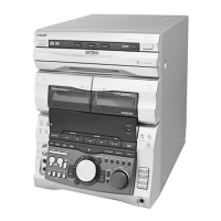
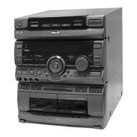
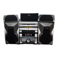
Description of all parts and controls on the front panel.

Clock and Timer Settings

Timer Function Setup Steps

Instructions for setting the internal clock for timer operations.

DISASSEMBLY

Loading Panel Removal

Steps to remove the loading panel assembly.

Front Panel Removal

Steps for removing the front panel.

DISASSEMBLY

Cassette Mechanism Deck Disassembly

Steps to disassemble the cassette mechanism.

Panel and Control Boards Removal

Steps to remove panel and control boards.

DISASSEMBLY

Disc Tray Removal

Steps to remove the disc tray assembly.

TEST MODE

Video CD Color-Bars Mode

Mode for checking video CD signals with color bars.

VIDEO BOARD IC502 Information

IC502 Component Differences and Replacement

Details differences between former/new IC502 types and replacement.

SERVICE MODE

Reset Functions

Covers MC Cold Reset and MC Hot Reset procedures.

CD Mechanism Modes

Includes CD Delivery and Sled Servo modes.

Operational and Indicator Modes

Covers Key Check, AM Tuner step, and Aging modes.

SERVICE MODE

Aging Mode Sequence and Operations

Details aging sequence for CD/Tape and operations.

MECHANICAL ADJUSTMENTS

Torque Measurement

Specifies torque values for tape deck components.

ELECTRICAL ADJUSTMENTS

Deck Section Adjustments

General notes and order for deck adjustments.

Head Azimuth Adjustment

Procedure to adjust playback head azimuth for decks.

ELECTRICAL ADJUSTMENTS

Tape Speed Adjustment (Deck A)

Procedure to set tape speed for deck A.

Playback Level Adjustment

Procedure to adjust playback levels for decks.

ELECTRICAL ADJUSTMENTS

Record Bias Adjustment (Deck B)

Procedure for adjusting tape recording bias for deck B.

Record Level Adjustment (Deck B)

Procedure for adjusting tape recording level for deck B.

CD SECTION

S Curve Check

Procedure to check S-curve waveform symmetry.

RF Level Check

Procedure to check RF signal level and waveform clarity.

CD SECTION

E-F Balance Traverse Check

Procedure to check E-F balance using remote commander.

VIDEO SECTION

Frequency Adjustment

Procedure to adjust video board frequency to 27MHz.

Related product manuals