EasyManua.ls Logo

Sony HCD-V919AV User Manual

Sony HCD-V919AV
100 pages
To Next Page IconTo Next Page
Page #1 background imageLoading...
Page #1 background image
MICROFILM
SERVICE MANUAL
MINI Hi-Fi COMPONENT SYSTEM
E Model
Chinese Model
SPECIFICATIONS
HCD-V919AV
This stereo system is equipped with the Dolby B-
type noise reduction system and Dolby Pro Logic
Surround decoder*.
* Manufactured under license from Dolby Labora-
tories Licensing Corporation.
DOLBY, the double-D symbol a and “PRO LOGIC”
are trademarks of Dolby Laboratories Licensing Cor-
poration.
HCD-V919AV is the Amplifier, Video CD
player, Tape Deck and Tuner section in
MHC-V919AV.
Model Name Using Similar Mechanism HCD-V717
CD Mechanism Type CDM38L-5BD24AL
Base Unit Name BU-5BD24AL
Optical Pick-up Name KSS-213D/Q-NP
Model Name Using Similar Mechanism HCD-V717
Tape Transport Mechanism Type
TCM-230AWR1/
230PWR1
CD
Section
Tape
Deck
Section
– Continued on next page –

Table of Contents

Question and Answer IconNeed help?

Do you have a question about the Sony HCD-V919AV and is the answer not in the manual?

Sony HCD-V919AV Specifications

General IconGeneral
TypeStereo System
Power Output100 W
CD PlayerYes
TunerAM/FM
BluetoothNo
USB PortNo
Speaker Configuration2.0
Output Power100 W
Frequency response20 Hz - 20 kHz
CD Player TypeSingle Disc
Cassette DeckYes
Remote ControlYes
FunctionsCD

Summary

SECTION 1 SERVICING NOTES

Self-Diagnosis and Component Handling

Unit self-diagnosis, optical pick-up, laser diode, chip component, and flex circuit board repair notes.

Safety Warnings and Precautions

Critical component warnings, laser safety, and chip component replacement notes.

SECTION 2 GENERAL

Control Panel Layout (Front & Rear Views)

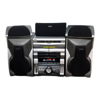
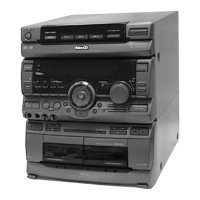
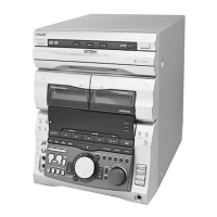
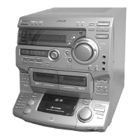
Identification of controls, buttons, knobs, and connectors on front and rear panels.

Setting Unit Time and Modes

Step-by-step guide for setting the unit's clock and accessing special modes.

SECTION 3 DISASSEMBLY

Panel and Tray Disassembly Procedures

Steps for removing loading panel, front panel, and disc tray.

Cassette Mechanism and Board Access

Procedures for disassembling cassette deck and accessing panel boards.

SECTION 4 TEST MODE

System Reset and Servo Test Modes

MC Cold/Hot Reset, CD Delivery, Sled Servo, and MW Tuner Step modes.

Operational and Video Test Modes

Aging mode for CD/Tape and VIDEO CD Color-bars mode.

SECTION 5 MECHANICAL ADJUSTMENTS

Torque Measurement Procedures

Specifications and methods for measuring tape mechanism torque.

SECTION 6 ELECTRICAL ADJUSTMENTS

Deck Section Adjustments

Precautions, Azimuth, Tape Speed, Playback Level, REC Bias/Level adjustments.

CD and Video Section Adjustments

CD section checks (S-Curve, E-F Balance, RF Level) and VIDEO frequency adjustment.

SECTION 7 DIAGRAMS

Block Diagrams Overview

Block diagrams for SERVO, AUDIO/VIDEO CD, TAPE DECK, and MAIN sections.

Schematic Diagrams

Schematics for BD, CD MOTOR, VIDEO, PANEL, and MIC/HEADPHONE sections.

IC Block Diagrams and Pin Functions

Internal IC block diagrams and detailed pin function descriptions.

Waveforms

Visual representations of key signal waveforms for BD and VIDEO boards.

SECTION 8 EXPLODED VIEWS

Unit Assemblies Exploded Views

Diagrams showing parts for Case, Chassis, Front Panel, CD, Tape, and Base Unit assemblies.

SECTION 9 ELECTRICAL PARTS LIST

Audio Board Component List

List of electronic components for the Audio board.

Main Board Component List

List of electronic components for the Main board.

Video Board Component List

List of electronic components for the Video board.

Related product manuals