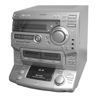
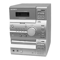
Do you have a question about the Sony HCD-VZ0 and is the answer not in the manual?
Key performance metrics for audio output, including DIN and RMS power.
Laser specifications for CD playback, including output, wavelength, and pick-up type.
Performance specifications for the tape deck section, including frequency response and wow/flutter.
Tuning ranges and intermediate frequencies for FM and AM radio reception.
Details on audio, video, and microphone input/output jacks and their specifications.
Power requirements, dimensions, mass, and supplied accessories for the unit.
Crucial handling notes for the optical pick-up block and laser diode emission checks.
Important safety warnings regarding hazardous radiation exposure and component replacement.
Details on the self-diagnosis function for VIDEO and AUDIO decoder sections via LED indicators.
Procedure for setting the system clock time, essential for timer functions.
Instructions on how to lock the CD mechanism for safe transport of the system.
Overview of available settings within the Sound Mode, including effects and equalizer.
Overview of available settings within the Setup Mode, covering various system configurations.
Instructions for removing the main case using screws and identifying screw types.
Procedure for disassembling the front panel, including connector and wire disconnections.
Procedures for MC Cold Reset and MC Hot Reset modes for clearing or resetting data.
Procedures for CD Service Mode (sled motor control) and VACS ON/OFF Mode.
Detailed checks performed on tape decks A and B during aging mode, including rewind and fast forward.
Sequence of CD operations performed during aging mode, such as tray rotation and track playback.
Procedure for using Video CD Color-Bars mode for video signal check via oscilloscope measurement.
Table detailing torque meter readings for various modes like FWD, REV, and tension adjustments.
Procedure for adjusting the record/playback head azimuth for optimal audio output.
Procedure for checking S-curve symmetry and peak-to-peak level for focus search.
Procedure for checking RF signal clarity and level, and removing connected wires.
Diagram showing the location of various circuit boards within the system, like MAIN, VIDEO, and TUNER units.
Illustrations of various waveforms for ICs in the Video section, related to playback and data transfer.
Block diagram detailing the Digital Servo and Digital Signal Processor functions in the BD section.
Block diagram of the Main section, covering sound processor, power amplifier, and tuner unit interfaces.
Printed wiring board layout for the BD board (Side A), showing component placement.
Printed wiring board layout for the BD board (Side B), indicating component placement.
Schematic diagram for the BD section, illustrating signal paths and component interconnections.
Printed wiring board layout for the Video board (Side A), showing component placement and test points.
Printed wiring board layout for the Video board (Side B), indicating component placement.
Schematic diagram of the Video section (1/3), detailing IC501, IC502, and related components.
Schematic diagram of the Video section (3/3), showing IC301, IC302, IC303, IC304, and their connections.
Printed wiring board layout for the Audio board, showing component placement and test points.
Schematic diagram of the Audio board, detailing playback and recording amplifier circuits.
Printed wiring board layout for the Main board, illustrating semiconductor locations and general component placement.
Schematic diagram of the Main section (1/3), showing master control, tuner unit, and power supply interfaces.
Printed wiring board layout for the Front Amp board, showing semiconductor and component placement.
Printed wiring board layout for the HP board, indicating headphone jack and related components.
Schematic diagram of the Front Amp section, showing power amplifier circuits and protection.
Schematic diagram for the HP board, detailing headphone output and related circuitry.
Printed wiring board layout for the Panel board, showing FL indicator tube and button switch components.
Schematic diagram of the Panel section, illustrating FL indicator tube driver and system control connections.
Printed wiring board layout for the Sub Panel board, showing button switches and controls.
Printed wiring board layout for the CD SW board, indicating button switches and volume controls.
Schematic diagram for the Sub Panel section, showing button switch circuits and LED drivers.
Schematic diagram for the CD SW board, illustrating switch circuits and volume control connections.
Printed wiring board layout for Sensor boards, showing disc detection switches and components.
Printed wiring board layouts for Clamp Motor and Load Motor boards, including connectors and encoders.
Schematic diagrams for CD mechanism components like sensors, switches, motors, and connectors.
Printed wiring board layout for the Trans board, showing AC input and transformer components.
Schematic diagram of the Trans board, illustrating power supply circuitry including transformer and voltage selector.
Printed wiring board layout for the MIC board, showing volume and echo controls, and ICs.
Schematic diagram of the MIC section, detailing amplifier and echo control circuits.
Printed wiring board layout for the Leaf SW board, showing motor control and switch components.
Schematic diagram for the Leaf SW section, illustrating motor control and switch signal paths.
Block diagrams for key ICs on the BD board, illustrating their internal functions and signal flow.
Block diagrams for key ICs on the Video board, showing functions like hue control and picture correction.
Block diagrams for key ICs on the Main board, detailing analog surround and power amplifier functions.
Block diagrams for key ICs on the MIC board, illustrating MIC amplifier and echo control functions.
Block diagrams for key ICs on the Panel board, showing system control and display driver functions.
Detailed pin assignments and functions for IC101 (Digital Signal Processor) on the BD board.
Detailed pin assignments and functions for IC502 (MPEG Decoder, Mechanism Control) on the VIDEO board.
Detailed pin assignments and functions for IC505 (CD Decoder, System Control) on the VIDEO board.
Detailed pin assignments and functions for IC401 (Master Control) on the MAIN board.
Detailed pin assignments and functions for IC701 (System Control) on the PANEL board.
Exploded view of the back panel section, showing all parts and their reference numbers for replacement.
Exploded view of the front panel section, listing all parts including buttons, knobs, and boards.
Exploded view of the chassis section, showing main boards, power cords, and adaptors.
Exploded view of the CD mechanism deck section (Part 1), detailing parts like screws, gears, and motors.
Exploded view of the CD mechanism deck section (Part 2), showing sliders, springs, and shafts.
Exploded view of the base unit section (BU-K2BD37A), showing the optical pick-up block and BD board.
Exploded view of the tape mechanism deck (TCM-230AWR12), detailing belts, flywheels, and motors.
List of electrical components for the Audio board, including capacitors, resistors, ICs, and connectors.
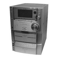
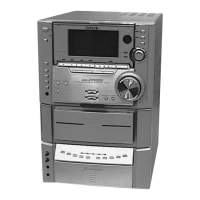
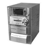
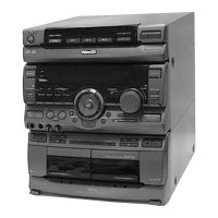
| Brand | Sony |
|---|---|
| Model | HCD-VZ0 |
| Category | Stereo System |
| CD Player | Yes |
| Remote Control | Yes |
| Bluetooth | No |
| USB Port | No |
| Cassette Deck | Yes |
| Functions | CD, Radio |
| Type | Mini Hi-Fi Component System |