3
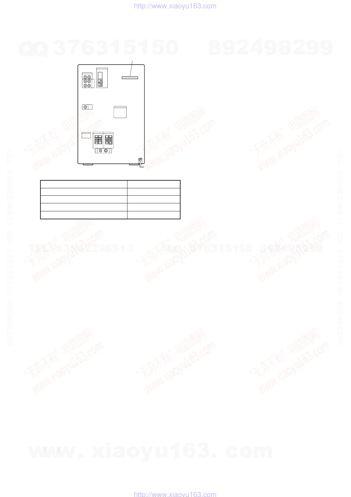
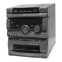
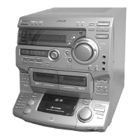
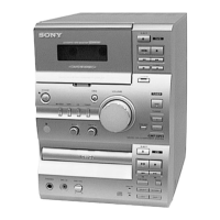
MODEL IDENTIFICATION
— BACK PANEL —
TABLE OF CONTENTS
1. SERVICE NOTE ······························································· 4
2. GENERAL ·········································································· 5
3. DISASSEMBLY
3-1. Case ···················································································· 8
3-2. Front Panel Section ···························································· 8
3-3. Tape Mechanism Deck Section (TCM-230AWR12) and
MIC Board ·········································································· 9
3-4. Back Panel Section ····························································· 9
3-5. Main Board, Front AMP Board ········································ 10
3-6. CD Base Unit (BU-K2BD37A) ········································ 10
3-7. CD Mechanism Deck Section (CDM53F-K2BD37A) ····· 11
3-8. Fitting Base (Guide) Assy, Bracket (Chassis) and
Fitting Base (Magnet) Assy ·············································· 11
3-9. Tray (Sub) ········································································· 12
3-10. Chassis (Mold B) Section, Stocker Section and
Slider (Selection) ······························································ 12
3-11. Gears Installation ······························································ 13
3-12. Slider (Selection) Installation ··········································· 13
3-13. Stocker Section Installation ·············································· 14
3-14. Chassis (Mold B) Section Installation ······························ 14
4. TEST MODE ···································································· 15
5. MECHANICAL ADJUSTMENTS ····························· 20
6. ELECTRICAL ADJUSTMENTS ······························· 20
7. DIAGRAMS
7-1. Circuit Board Location ····················································· 25
7-2. Block Diagrams ································································ 28
7-3. Printed Wiring Board – BD Section – ······························ 32
7-4. Schematic Diagram – BD Section – ································· 33
7-5. Printed Wiring Board – Video Section – ·························· 34
7-6. Schematic Diagram – Video Section (1/3) – ···················· 35
7-7. Schematic Diagram – Video Section (2/3) – ···················· 36
7-8. Schematic Diagram – Video Section (3/3) – ···················· 37
7-9. Printed Wiring Board – Deck Section – ··························· 38
7-10. Schematic Diagram – Deck Section – ······························ 39
7-11. Printed Wiring Board – Main Section – ··························· 40
7-12. Schematic Diagram – Main (1/3) Section – ····················· 41
7-13. Schematic Diagram – Main (2/3) Section – ····················· 42
7-14. Schematic Diagram – Main (3/3) Section – ····················· 43
7-15. Printed Wiring Board – AMP Section – ··························· 44
7-16. Schematic Diagram – AMP Section – ······························ 45
7-17. Printed Wiring Board – Panel Section – ··························· 46
7-18. Schematic Diagram – Panel Section – ····························· 47
7-19. Printed Wiring Board – Switch Section – ······················· 48
7-20. Schematic Diagram – Switch Section – ··························· 49
7-21. Printed Wiring Board – CD Mechanism Section – ·········· 50
7-22. Schematic Diagram – CD Mechanism Section – ············· 51
7-23. Printed Wiring Board – Power Supply Section – ············· 52
7-24. Schematic Diagram – Power Supply Section – ················ 53
7-25. Printed Wiring Board – MIC Section – ···························· 54
7-26. Schematic Diagram – MIC Section – ······························· 54
7-27. Printed Wiring Board – Leaf SW Section – ····················· 55
7-28. Schematic Diagram – Leaf SW Section – ························ 55
7-29. IC Block Diagrams ··························································· 56
7-30. IC Pin Descriptions ·························································· 58
8. EXPLODED VIEWS
8-1. Back Panel Section ··························································· 69
8-2. Front Panel Section ·························································· 70
8-3. Chassis Section ································································· 71
8-4. CD Mechanism Deck Section-1 (CDM53F-K2BD37A) ·· 72
8-5. CD Mechanism Deck Section-2 (CDM53F-K2BD37A) ·· 73
8-6. Base Unit Section (BU-K2BD37A) ································· 74
8-7. Tape Mechanism Deck Section (TCM-230AWR12) ········ 75
9. ELECTRICAL PARTS LIST ······································· 76
• Abbreviation
SP : Singapore model
MY : Malaysia model
HK : Hong Kong model
TH : Thai model
EA : Saudi Arabia model
MODEL
SP, MY models
HK model
TH model
EA model
PARTS No.
4-226-747-3s
4-226-747-4s
4-226-747-5s
4-226-747-6s
Parts No.
w
w
w
.
x
i
a
o
y
u
1
6
3
.
c
o
m
Q
Q
3
7
6
3
1
5
1
5
0
9
9
2
8
9
4
2
9
8
T
E
L
1
3
9
4
2
2
9
6
5
1
3
9
9
2
8
9
4
2
9
8
0
5
1
5
1
3
6
7
3
Q
Q
TEL 13942296513 QQ 376315150 892498299
TEL 13942296513 QQ 376315150 892498299
http://www.xiaoyu163.com
http://www.xiaoyu163.com