6
HCD-VX555/VX555J
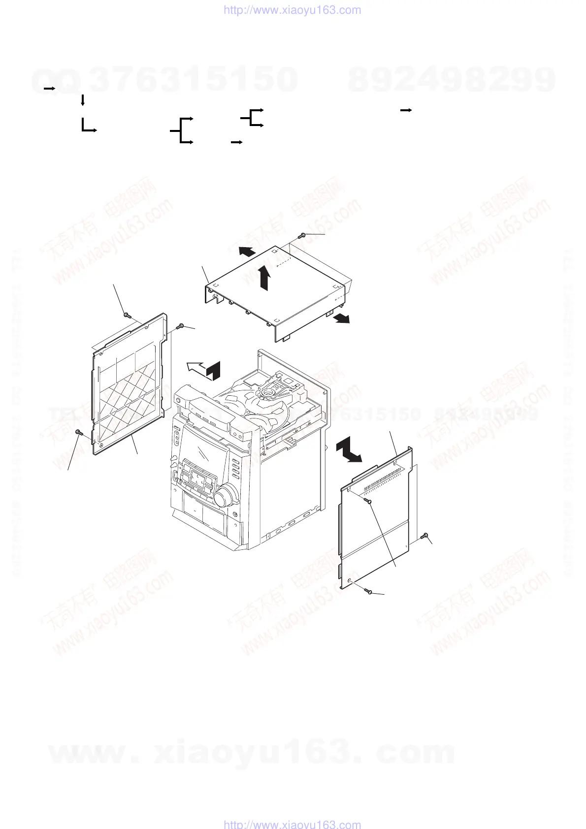
SECTION 2
DISASSEMBLY
Note : Follow the disassembly procedure in the numerical order given.
2-1. UPPER CASE (TOP)
• The equipment can be removed using the following procedure.
VIDEO board, Driver board, Moter board and Address sensor board
Upper case (Top)
Loading panel assy
Front panel section
Panel board
Sub trans board and Main trans board Main board and Power boar
Leaf SW board, Head (A) board and Head (B) board
Base unit
Set
Side panel (R)
4
qa
q;
q;
8
Case (Top)
Side panel (L)
5
Two screws (Case)
7
Two screws
(+BVTP 3
×
10)
3
Two
screws
(+BVTP 3
×
10)
1
Two screws (Case)
9
Four screws (+BVTP 3
×
16)
6
Screw (Case)
2
Screw (Case)
w
w
w
.
x
i
a
o
y
u
1
6
3
.
c
o
m
Q
Q
3
7
6
3
1
5
1
5
0
9
9
2
8
9
4
2
9
8
T
E
L
1
3
9
4
2
2
9
6
5
1
3
9
9
2
8
9
4
2
9
8
0
5
1
5
1
3
6
7
3
Q
Q
TEL 13942296513 QQ 376315150 892498299
TEL 13942296513 QQ 376315150 892498299
http://www.xiaoyu163.com
http://www.xiaoyu163.com