EasyManua.ls Logo

Sony HCD-WZ5 User Manual

Sony HCD-WZ5
46 pages
To Next Page IconTo Next Page
Page #1 background imageLoading...
Page #1 background image
HCD-WZ5
AEP Model
UK Model
E Model
Australian Model
SERVICE MANUAL
COMPACT DISC TUNER
SPECIFICATIONS
Ver 1.0 2003. 04
HCD-WZ5 is the tuner, and CD
section in MHC-WZ5.
CD player section
System Compact disc and digital
audio system
Laser Semiconductor laser
(λ=780 nm)
Emission duration:
continuous
Frequency response 2 Hz – 20 kHz (±0.5 dB)
Wavelength 780 – 790 nm
Signal-to-noise ratio More than 90 dB
Dynamic range More than 90 dB
OPTICAL CD DIGITAL OUT (European and
Australian models only)
(Square optical connector jack, rear panel)
Wavelength 660 nm
Tuner section
FM stereo, FM/AM superheterodyne tuner
FM tuner section
Tuning range 87.5 – 108.0 MHz
antenna FM lead antenna
antenna terminals 75 ohms unbalanced
Intermediate frequency 10.7 MHz
AM tuner section
Tuning range
European model: 531 – 1,602 kHz
(with the tuning interval
set at 9 kHz)
Latin American model:
Other model:
General
Power requirements
Power consumption
European model: 150 watts
0.3 watts (at the Power
Saving Mode)
Except for European model:
180 watts
Dimensions (w/h/d)
CD player/Tuner:
Approx. 255 × 1 35 ×
355 mm
Mass
CD player/Tuner: Approx. 2.8 kg
Design and specifications are subject to change
without notice.
Power
voltage
is
D
9V
and
fed
with
STEREO
CASSETTE
DECK
AMPLIFIER
(DXA-WZ5)
from the external SYSTEM CONTROL connectors.
530 – 1,710 kHz
(with the tuning interval
set at 10 kHz)
531 – 1,710 kHz
(with the tuning interval
set at 9 kHz)
530 – 1,710 kHz
(with the tuning interval
set at 10 kHz)
531 – 1,602 kHz
(with the tuning interval
set at 9 kHz)
antenna AM loop antenna
antenna terminals External antenna terminal
Intermediate frequency 450 kHz
Sony Corporation
Home Audio Company
Published by Sony Engineering Corporation
9-877-331-01
2003D1600-1
© 2003.04
Model Name Using Similar Mechanism NEW
CD CD Mechanism Type CDM77B-K6BD47S
Section Base Unit Name BU-K6BD47S
Optical Pick-up Name KSS-213D
w
w
w
.
x
i
a
o
y
u
1
6
3
.
c
o
m
Q
Q
3
7
6
3
1
5
1
5
0
9
9
2
8
9
4
2
9
8
T
E
L
1
3
9
4
2
2
9
6
5
1
3
9
9
2
8
9
4
2
9
8
0
5
1
5
1
3
6
7
3
Q
Q
TEL 13942296513 QQ 376315150 892498299
http://www.xiaoyu163.com
Question and Answer IconNeed help?

Do you have a question about the Sony HCD-WZ5 and is the answer not in the manual?

Sony HCD-WZ5 Specifications

General IconGeneral
BrandSony
ModelHCD-WZ5
CategoryTuner
LanguageEnglish

Summary

General

Main Unit Controls and Descriptions

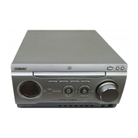
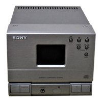
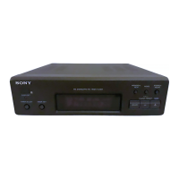
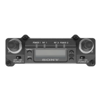
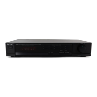
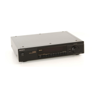
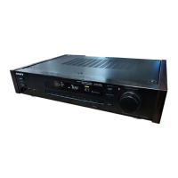
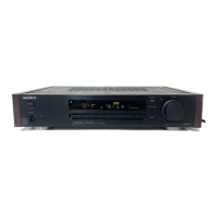
Overview of the main unit's controls, buttons, and their functions.

Disassembly Procedures

Case Removal

Procedure for removing the main case of the HCD-WZ5 unit.

Front Panel Assembly Disassembly

Step-by-step guide for disassembling the front panel assembly.

Board Component Disassembly

Instructions for removing various internal boards like PANEL, TUNER, MAIN, etc.

Mechanism and Unit Disassembly

Procedures for disassembling the CD mechanism deck, tray, base unit, and optical pick-up.

Electrical Adjustments

CD Section Adjustments

Procedure for checking and adjusting the CD section's focus bias.

Focus Bias Check Procedure

Detailed steps for performing the focus bias check using an oscilloscope.

Test Modes

Reset Procedures

Covers Cold Reset, MD/VIDEO, AM Channel Step, and CD Ship Modes.

Special Operational Modes

Details on Disc Tray Lock, GC Test, VACS Level, Display Check, and VACS ON/OFF modes.

Diagrams

Circuit Board Locations

Diagram showing the physical location of various circuit boards within the unit.

Waveform Illustrations

Illustrations of waveforms for CD Board and MAIN Board, showing signal characteristics.

Exploded Views

Front Panel Assembly Exploded View

Exploded view of the front panel section, showing all components and their part numbers.

Chassis Assembly Exploded View

Exploded view detailing the chassis section and its associated parts.

CD Mechanism Exploded View

Exploded view of the CD mechanism deck, including optical pick-up and tray.

Optical Pick-Up Exploded View

Exploded view specifically for the optical pick-up (KSM-213DCP/Z-NP).

Electrical Parts List

Board Components

List of components for the BACK-LIGHT BOARD, including resistors and capacitors.

Capacitor Specifications

List of capacitors with their part numbers, types, capacitance, and voltage ratings.

Semiconductor Components

List of semiconductors (diodes, transistors) with part numbers and locations.

Related product manuals