SERVICE
MANUAL
US Model
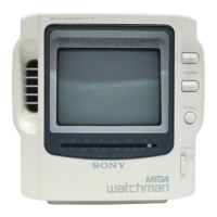
color
watchman
SPECIFICATIONS
TV standard
American TV standard
Color system NTSC
Channel coverage
VHF channel 2-13
UHF channel 14-69
Radio frequency range
FM: 87.6-108 MHz (Stereo).
AM: 530-l ,710
kHz
(Mono)
Antenna VHF/UHF/FM: telescopic antenna
AM: built-in ferrite bar antenna
Display
TN LCD/TFT active matrix method
Effective picture-element ratio: more than 99.99%
Picture size 3-inch picture measured diagonally
Speaker
36 mm (1
7/16
inches) dia.
EXT ANT: minijack, impedance 75 ohms (for TV/FM-radio)
A/V IN: tripolar minijack, impedance audio 47 kilohms/
video 75 ohms
output
(headphones): stereo minijack, impedance 8-300 ohms
Power requirement 9 V DC, See “Power sources”. (page 3)
Battery life
See “Power sources”.
Power consumption 3.8 W (9 V DC) AC adaptor use
Dimensions Approx.l13.6 x 166.1 x 60 mm (w/h/d)
(4
1/
2
x 6
1/
2
x 2
3/
8 inches)
incl.
projecting parts
Weight Approx. 0.58 kg (1 lb 4 oz) incl. batteries
Approx. 0.45 kg (1 lb) excl. batteries
Accessories supplied
AC power adaptor
(l),
Sun shade
(l),
Carrying pouch (1)
Optional accessories
Alkaline battery size AA (LR 6)
AV cord
AVK-715M
Car antenna VCA-SE
Headphones
MDR-34
Car battery cord DCC-E19OL
Design and specifications subject to change without notice.
LCD
COLORTV=AM/FMSTEREOTUNER
SONY@