SECTION 3
ELECTRICAL ADJUSTMENTS
is-
- 1. TV SECTION
1.
2.
3.
4.
5.
6.
7.
PRECAUTION
Make adjustment in sequence as described.
Power supply voltage is + 9.0 + O.lV (DC jack end) unless
otherwise specified. Power supply shall not be input
overlapped.
Check the error in waveform and screen for adjustment.
Measure a fluorescent tube and an liquid crystal display
module device by connecting them with the A board.
Unless otherwise specified, input the color bar signal, etc.
from A/V IN jack
(J301)
by using AV-cord
(AVK-715M,
etc.) to intercept the internal TV detection output. Also,
usually use monochromatic gradation wave mono scope
with
chroma
signal OFF.
Measuring instruments
l NTSC pattern generator
l Digital multitester
l Oscilloscope
l Frequency counter
Modes of Switches and Control
S601
(POWER)
•**~~~~~******TV
SlOl
(TV BAND) l . . . l . l l l . . VHF
RV401
(VOL)
. . . . . . . . . . . . . .
..minimum
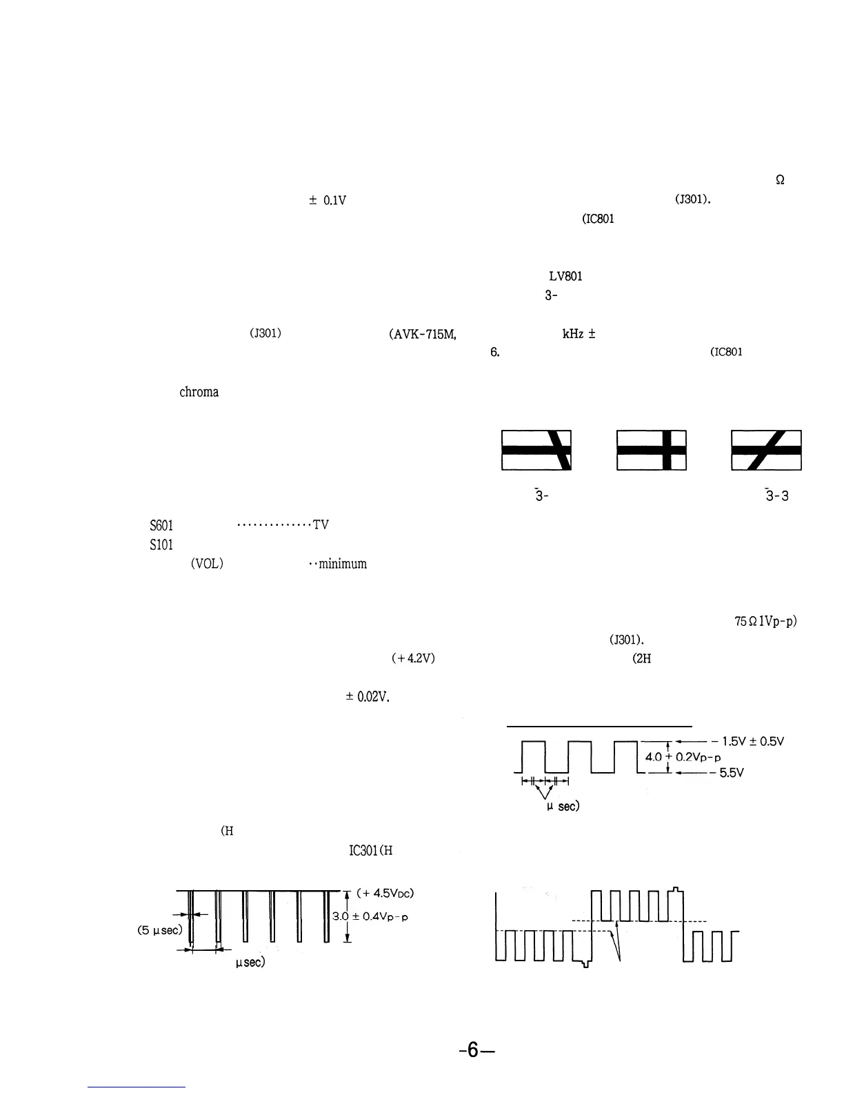
VOLTAGE ADJUSTMENT
1. input the pattern generator (Color chart,
75Q
lVp-p) to
Procedure:
the A/V IN jack
(J301).
1. Connect a digital multitester between TP213 (+4.2V) and
(GND) on the A board, and then adjust RV602 so that
the reading of the voltage is + 4.2
t
0.02V.
Connect an oscilloscope (DC) to TP513 (COM) to check
2. Common signal check
(2H
cycle)
if the waveform is as shown in the following figure.
Adjustment Location:
A BOARD
WAVEFORM CHECK
H pulse check
(H
cycle)
Connect an oscilloscope to Pin 21 of
IC301
(H
PULSE) to
check if the waveform is as shown in the following figure.
(5
vsec)
(about 63.5 psec)
.
HORIZONTAL AFC ADJUSTMENT
Procedure:
1.
2.
3.
4.
5.
6,
7.
Input the pattern generator (monoscope, ‘75
Q
and
1 Vp-p) to the A/V IN jack
(J301).
Short TP502
(IC801
pin 10) to GND.
The horizontal and vertical synchronization lines start
moving.
Adjust
LV801
so that these lines stop moving.(Refer to
Figure 3- 2.)
Check that the frequency counter connected to TP505
is 15.734
kHz
+
60 Hz.
Disconnect the line between TP502
(IC801
pin 10) and
GND.
Check that the lines are in the display frame and the
synchronization is stable.
E3
No good Good
Fig.
3-
1
No good
Fig. 3-2
Fig.
3-3
m
H
COMMON SIGNAL VOLTAGE ADJUSTMENT and HUE
CHECK
Procedure:
GND electric potential
(63.5
p
set)
3. Check that the blue signal output is as follows. (Chroma
demodulation)
If not, adjust RV306 (HUE Control).
These levels
are
almost the same.
6-
 Loading...