Notes on chip component replacement
TABLE OF CONTENTS
l
Never reuse a disconnected chip component.
l
Notice that the minus side of a tantalum capacitor may
Set tion
Title Page
be damaged by heat.
Flexible Circuit Board Repairing
1. GENERAL
. . . . . . . . . . . . . . . . . . . . . . . ..*................
3
l
Keep the temperature,of the soldering iron around
2. DISASSEMBLY
270
“C
during repairing.
2-
1.
Cabinet
(Rear)
Assy
. . . . . . . . . . . . . . . . . . . l l . l l
4
l
Do not touch the soldering iron on the same conductor
2-2. A, R Boards
. . . . . . . . . . . . . . . . . . . . . . . . . . . . . . . . .
4
of the circuit board (within 3 times).
l
Be careful not to apply force on the conductor when
2-
3.
Indicator Module (LCD) l l l l l l l l l l l l l l l l l l . l 5
soldering or unsoldering.
2-J.
Dial
pointer
Setting.........................
5
3. ELECTRICAL ADJUSTMENTS
3-l. TV Section
. . . . . . . . . . . . . . . . . . . . . . . . . . . . . . . . . . .
6
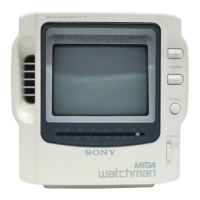
Features
3-2. Radio Section
. . . . . . . . . . . . . . . . . . . . . . . . . . . . . . . .
8
l
The LCD (Liquid Crystal Display) provides clear pictures and natural
facial color tones.
l
It is used as an AV (audio/video) monitor.
l
The voltage synthesizer tuning system allows easy tuning.
l
Grip and stand are provided for cohvenient use.
l
The new power circuit and fluorescent lamp provide long
battery life (approx. 5 hours with alkaline batteries).
4. DIAGRAMS
4- 1. Block Diagram
. . . . . . . . . . . . . . . . . . . . . . . . . . . . . .
11
4-
2.
Semiconductor Lead Layouts . l l . . l . . . l l . l . l 14
J-3.
printed
Wiring
Board.......................
17
4-4. Schematic Diagrams.........................
21
Note to CATV system installer in the U.S.A.:
-
This reminder is provided to call the CATV system installer’s attention to
Article 820-40 of the NEC that provides guidelines for proper grounding
and, in particular, specifies that the cable ground shall be connected to
the grounding system of the building, as close to the point of cable entry
as practical.
4- 5. IC Block Diagrams
..........................
21
4- 5. IC Description
...............................
23
5. EXPLODED VIEWS
5- 1. Cabinet Section
.............................
25
5- 2. Display Section
.............................
26
6. ELECTRICAL PARTS LIST
. . . . . . . . . . . . . . . . . . . . . . . . . .
27