4-
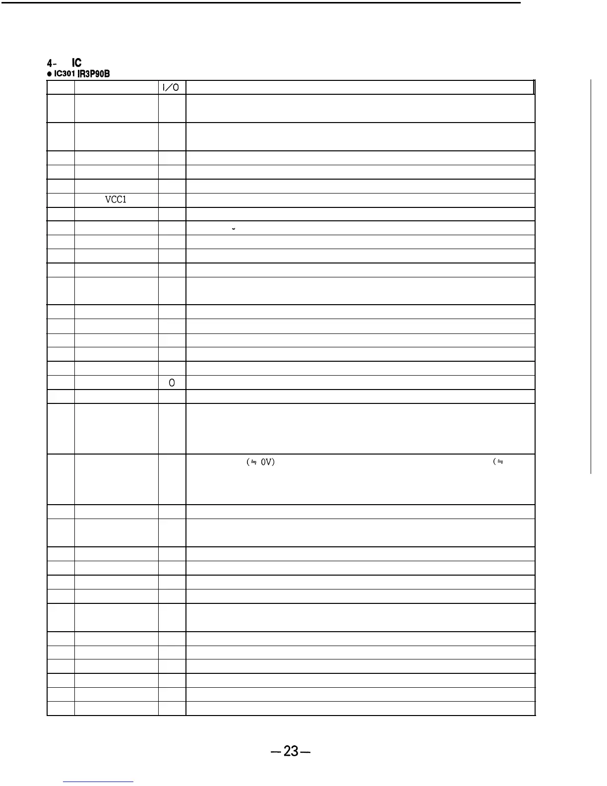
6. IC DESCRIPTION
a
IC301
IR3P90B
(A BOARD)
No.
Pin Name
I/O
Description
1
SW
I
This pin switches between the signal from the tuner block (INT), video, and signal
from EXT R.G.B input pin (EXT). L : INT, H : open or EXT.
2
CONT
I
The contrast of the primary color output can be adjusted by the DC voltage input
to this pin.
3
EXT IN B
I
No signal.
4
EXT IN G
I
VHF tuning display bay signal input.
5
EXT IN R
I
UHF tuning display bay signal input.
6
VCCl
Positive polarity power supply connection.
7
VEE
Negative polarity power supply connection.
8 N.C.
Not used.
-
9 ACC FILTER
I
The ACC detection filter is connected.
10 VIDEO IN
I
The video signal is input.
11
COLOR
I
Color is adjusted by the DC voltage input at this pin.
12
F ADJ
I
The frequency characteristics of the filter can be adjusted by the resistance value
which is connected between this pin and GND.
13 AGC OUT
0
Not used.
14 AGC FILTER
I
The AGC detection filter of the video block is connected.
15 TRAP OUT
0 The 3.58 MHz trap is connected.
16
CLAMP
I
The capacitance which clamps the pedestal of the Y- signal is connected.
17
APL
I
The filter which detects the APL (Average Picture Level) of the Y-signal is connected.
18
H FILTER OUT
0
The video signal which separates the sync signal is output.
19
SYNC SEP
I
Sync signal separation circuit input. The video signal is input.
This pin outputs the sync signal which is separated at the sync circuit. The output
20 SYNC OUT
0
type is the open collector type. Therefore, it is possible to connect this pin to the
controller powered by another supply. The output signal is H when it is sync, and
L when it is not sync.
The L pulse
(*
OV)
is input when the sync signal is locked, and H pulse
(*
3V) is
21
H. PULSE IN
I
input when. the sync signal is not locked. The sync signal which is input, and the sync
signal which is separated at the sync separation circuit are OR and input to the pulse
generator circuit.
22 TIME CONST
I
The gate pulse width is set with the CR time constant.
23 PICTURE
I
The frequency characteristics of the video block can be adjusted by the DC voltage
which is input to this pin.
24
KILLER FILTER I The killer detection filter is connected.
25
TINT
I
The color phase can be adjusted by the DC voltage which is input at this pin.
26
vco
The crystal oscillator is connected.
27
APC F
I
The APC detection filter is connected.
28 COM AMP
I
The COMMON output amplitude can be adjusted by the DC voltage which is input
at this pin.
29 GND GND
30 COM OUT
0
This pin outputs the pulse which drives the common electrode of the LCD.
31 VEE Negative polarity power supply pin.
32
R OUT 0 The inverted primary color signal is output according to the inversion signal.
33
vcc2
Positive polarity power supply connection
34
G OUT 0 The inverted primary color signal is output according to the inversion signal.
-23-