Do you have a question about the Sony STR-NX3 and is the answer not in the manual?
Lists component models composing the MHC-NX1/NX3AV system.
Provides a comprehensive list of replacement parts for the unit.
Technical specifications for the CD player, including laser output and frequency response.
Technical specifications for the tape deck, including frequency response and output level.
Important notes and precautions for servicing the appliance.
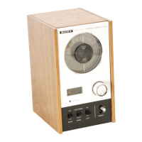
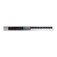
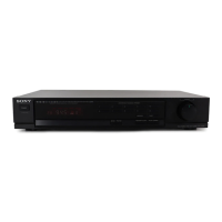
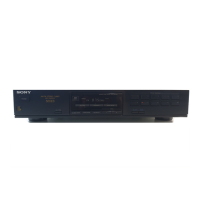
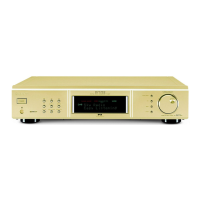
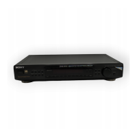
General information about the unit, including controls and model identification.
Instructions for supplying power during servicing procedures.
Step-by-step instructions for disassembling the unit for repair.
Guide for cleaning the optical pick-up lens assembly.
Steps for removing the main outer case of the unit.
Steps for disassembling the front panel assembly.
Procedure for removing the CD mechanism deck.
Procedure for removing the tape deck mechanism.
Exploded view and parts for the CD base unit.
Exploded view of the main chassis and its components.
Tests all LEDs and checks button functionality.
Moves optical pick-up for shipping; used after repair.
Tests tape deck functions and amplifier status.
Resets all user data and settings to factory defaults.
Performs automated operational checks on CD and tape deck sections.
Specifies torque values for mechanical component adjustments.
Electrical adjustments for the tape deck's recording and playback.
Procedure to align playback heads for optimal signal clarity.
Adjusts tape speed for accurate frequency response.
Adjusts playback signal levels for L-CH and R-CH channels.
Adjusts recording bias for tape decks to optimize recording quality.
Adjusts recording signal levels for tape decks.
Notes on interpreting wiring boards and schematic diagrams.
Checks S-curve waveform symmetry and peak-to-peak levels.
Checks the clarity and level of the RF signal waveform.
Component layout for the BD board.
Circuit schematic for the BD board.
Component layout for CD motor/sensor sections.
Circuit schematic for CD motor/sensor sections.
Component layout for the AUDIO board.
Circuit schematic for the AUDIO board.
Component layout for the LEAF SW board.
Circuit schematic for the LEAF SW board.
Component layout for the MAIN board.
Part 1 of the MAIN board circuit schematic.
Part 2 of the MAIN board circuit schematic.
Component layout for PANEL sections.
Circuit schematic for PANEL sections.
Details pin functions for ICs on the MAIN board.
Illustrates typical waveforms for various test points.
Shows block diagrams for key ICs on the BD board.
Exploded view of the main unit chassis and related parts.
Exploded view of the front panel assembly and its components.
Exploded view of the CD mechanism deck section 1.
Exploded view of the CD mechanism deck section 2.
Exploded view of the CD base unit section.
Exploded view of the tape mechanism deck section 1.
Exploded view of the tape mechanism deck section 2.
List of electrical parts for the AUDIO board.
List of electrical parts for the PA board.
List of electrical parts for the MAIN board.
List of electrical parts for the PANEL sections.
List of electrical parts for the TRANS board.